Official distribution in Spain

Guide bushes
and ball cages

The elements that, together with the guide pillar, align the two halves of a stamping die. Complete Steinel Normalien range with seven guide types and load capacities certified to DIN ISO 14728-1.

FIG · plain guide bush family
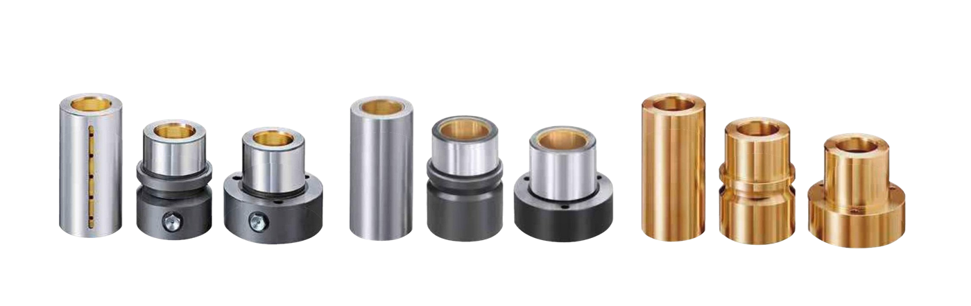
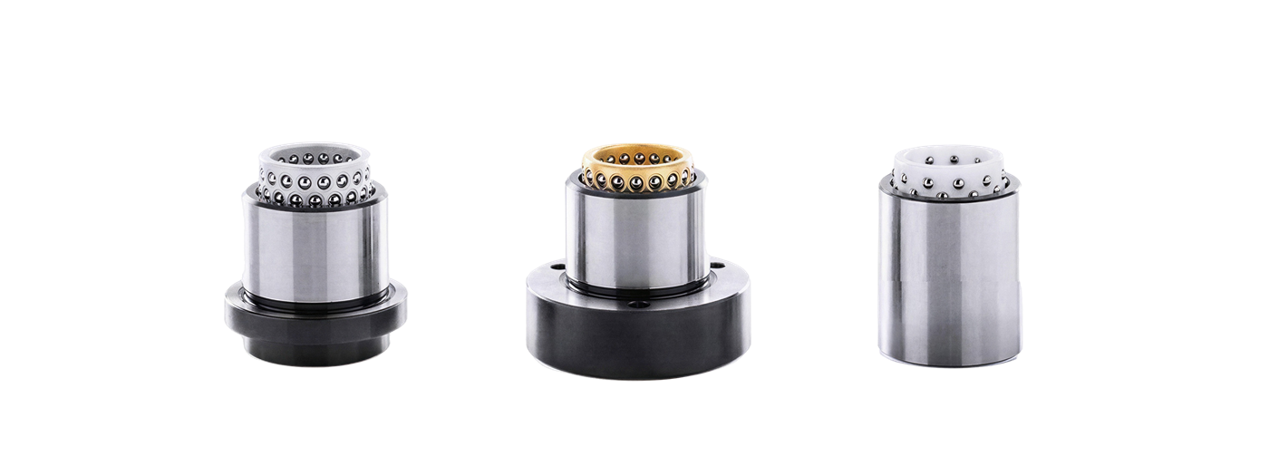
Complete family of Steinel Normalien plain guide bushes — three variants in their three mounting configurations (smooth, shoulder, flange)
Guide types
7 · plain + rolling
Combinations
126 per mounting Ø
Load capacity
DIN ISO 14728-1
Bush standards
DIN 9831 / ISO 9448
01

What are guide bushes and ball cages?

Guide bushes and ball cages are the components that work paired with the guide pillar to ensure alignment between the upper and lower die shoe during every press stroke. This alignment, held to instrumentation tolerances, determines the cutting clearance between punch and die and, by extension, the edge quality of the stamped part and the service life of the tool.

Surisa distributes the complete range of Steinel Normalien GmbH in Spain, a leading German manufacturer of standardized die-set components. The products comply with DIN 9831 / ISO 9448 for guide bushes and DIN ISO 14728-1 for the dynamic load capacity of the cages.

02

Plain guide vs ball guide vs roller guide

The three available guide technologies cover complementary working ranges. The choice is not a matter of quality but of suitability for the application.

Comparison of the three guide technologies (plain, ball cages, and roller cages) by stroke, allowable side thrust, speed, and maintenance.
TechnologyStrokeSide thrustSpeedMaintenance
PlainFull pillar strokeHigh — distributed over the surfaceUp to 20 m/minPeriodic lubrication or solid lubricant
Ball cagesLimited by the cage (Stroke/2 rule)Medium30–40 m/min and aboveAlmost none
Roller cagesLimited by the cage (Stroke/2 rule)Very high — 6–12× a ball of the same Ø≥ 40 m/minAlmost none

Stroke/2 rule. In rolling guides, during the stroke the cage advances half the axial travel of the bush. This limits the usable stroke to that available between the cage and the mechanical stops of the assembly.

03

Single mounting diameter: 126 interchangeable combinations

The main advantage of the Steinel Normalien system is that all bushes share the same external diameter within a mounting family. A die set designed for a plain guide can be converted into a die set with a ball guide without additional machining operations — you simply replace the bush.

2
guide diameters
internal diameter
7
guide types
3 plain + 4 rolling
3
mounting configurations
smooth · shoulder · flange
3
bush lengths
by series
126
combinations per mounting Ø

What type of guide does your die need?

Our engineers help you choose between a plain guide, ball cage, or roller cage based on side thrust, stroke, and working speed.

04

Plain guide — three variants

The three plain technologies share the mounting geometry but differ in the lubrication system and materials. Click each type to expand its data.

01 Steel with bronze coatingSteel / bronze
Three steel guide bushes with a bronze coating — smooth, shoulder, and flange configurations
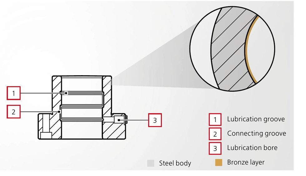
Section of the internal lubrication system: lubrication groove (1), connecting channel (2), and lubrication hole (3), with a steel body / bronze layer legend
Diseño
  • The hardened steel body (63 HRC) absorbs side loads and prevents the bush from deforming under heavy load application.
  • The galvanic bronze layer on the running surface is very hard (250–300 HV), of minimal wear, and honed to the highest surface quality.
  • Excellent thermal conductivity to quickly dissipate friction heat.
  • The internal lubrication system consists of parallel grooves joined by connecting channels.
Lubricación
  • The internal system design ensures uniform lubricant distribution across the entire sliding surface and effectively protects against dirt.
  • Depending on the guide load, it must be periodically resupplied with high-performance lubricant (SZ9850 / SZ9853); it accepts connection to a centralized lubrication system.
Usos
  • Suitable for long strokes, high side thrust, and contamination-prone environments.
  • Sliding speed up to 20 m/min.
  • With an optimal design of lubrication, clearance, stroke, radial load, and heat dissipation, frequencies of up to 800 strokes/min are possible.
  • Guide clearance of 2–7 µm (Ø 32 mm) — for greater clearance, specify when ordering.
  • Dry-running properties available.
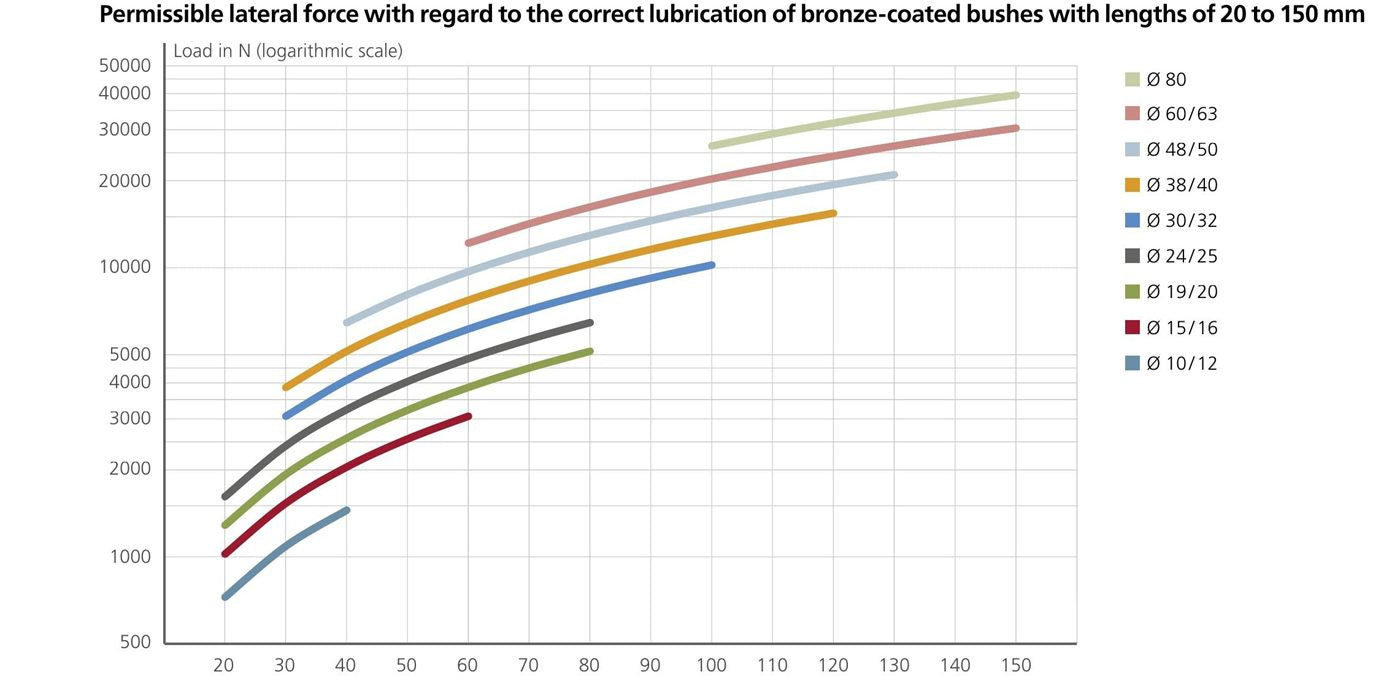
GRÁFICO · Allowable side thrust (N, log. scale) vs bush length 20–150 mm · curves by Ø
Chart of allowable side thrust (N, logarithmic scale) against bush length (20–150 mm), with one curve per diameter
02 With solid lubricantSolid lubricant
Three guide bushes with solid lubricant — smooth, shoulder, and flange configurations
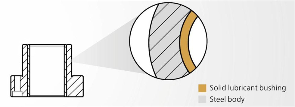
Section of the steel body with a sintered bronze sleeve CuSn10 with MoS₂, with a solid lubricant bushing / steel body legend
Diseño
  • The hardened steel body (63 HRC) supports the solid lubricant bushing, takes up the side loads, and prevents the bush from deforming under heavy load.
  • The integrated sintered bronze bushing (CuSn10) with solid lubricant (MoS₂) is self-lubricating and low-maintenance.
  • The bushing has a hardness of 65 HV: of minimal wear and honed to the highest surface quality.
Lubricación
  • The sintered bronze with solid lubricant takes over the lubricating function between bush and pillar.
  • The lubricant film uniformly covers the entire inner wall of the bush.
  • The adherent, coherent film prevents corrosion of the bush and pillar during shutdown or startup.
Usos
  • Also suitable for extremely small strokes and radial movements.
  • Sliding speed up to 20 m/min.
  • Guide clearance of 3–10 µm (Ø 32 mm) — for greater clearance, specify when ordering.
  • Optimal for low-maintenance applications.
  • Excellent dry-running properties.
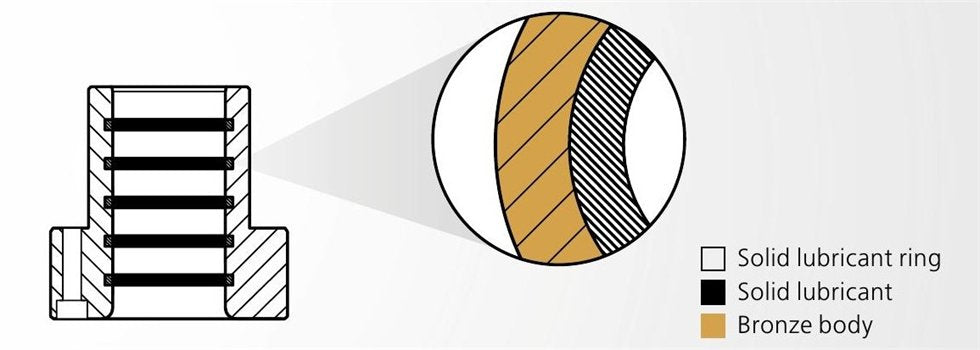
03 Bronze with solid lubricant ringsGraphite rings
Three CuZn25Al5 bronze guide bushes with graphite rings — smooth, shoulder, and flange configurations
Section with the solid lubricant rings distributed lengthwise, with a solid lubricant ring / solid lubricant / bronze body legend
Diseño
  • The bronze guides (CuZn25Al5) with integrated graphite rings (soaked in hydraulic oil) are self-lubricating and low-maintenance.
  • With a hardness of class 22 HRC, the bushes stand out for their high stability.
  • Several solid lubricant rings are integrated flush with the sliding surface inside the bush.
  • Excellent thermal conductivity to quickly dissipate friction heat.
  • The self-lubricating system significantly reduces maintenance cost.
Lubricación
  • The solid lubricant contained in the rings takes over the lubricating function between bush and pillar.
  • The adherent, coherent film prevents corrosion of the bush and pillar during shutdown or startup.
Usos
  • Suitable for axial movements with a wide stroke.
  • To ensure an optimal film, the stroke must always be greater than the distance between the solid lubricant rings.
  • Sliding speed up to 20 m/min.
  • Guide clearance of 3–10 µm (Ø 32 mm) — for greater clearance, specify when ordering.
  • Optimal for low-maintenance applications.
  • Dry-running properties required.
05

Precision ball cages

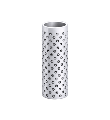
Ball cages (ball cage retainers) replace sliding contact with rolling contact. The precision hardened steel balls are arranged in an axial spiral, so that each ball travels its own raceway — this increases service life by avoiding repeated indentation.

  • Free installation position. The aluminum, brass, and plastic cages allow longitudinal and rotational movements.
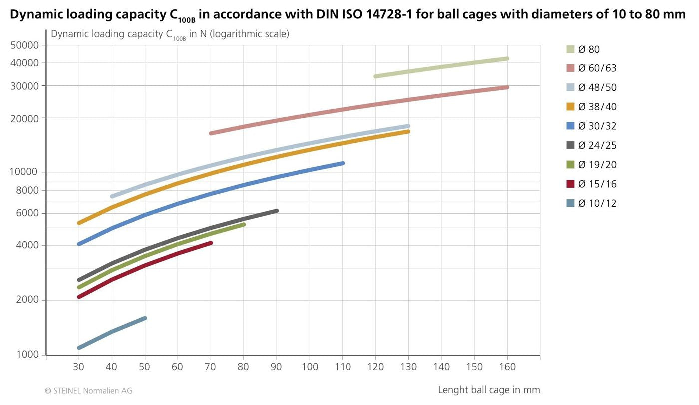
  • Load capacity C₁₀₀B. Certified to DIN ISO 14728-1 · Ø 10–80 mm · cage length up to 160 mm.
  • Preload. Adjustable to the guide diameter.
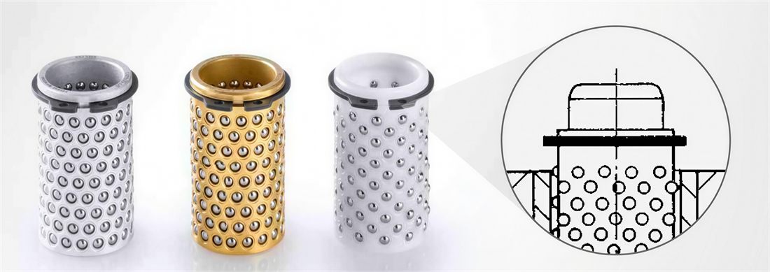
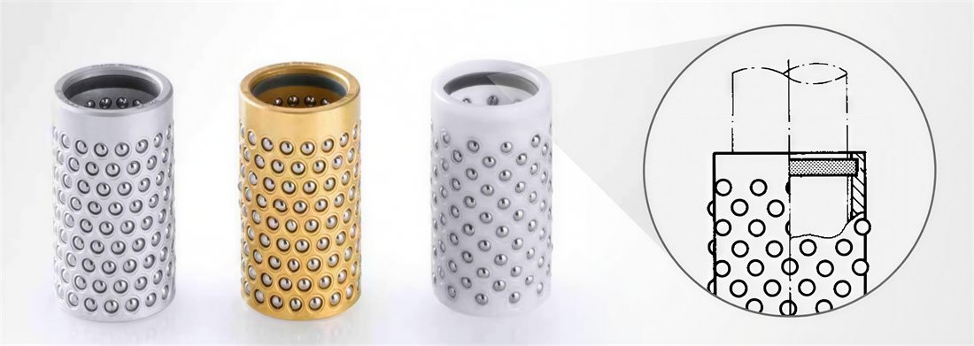
FIG · 3 materials
The three Steinel ball cages — aluminum (black), brass (gold), and plastic (white) — with the balls arranged in an axial spiral
CHART · dynamic load capacity C₁₀₀B (DIN ISO 14728-1) · Ø 10–80 mm
Chart of dynamic load capacity C₁₀₀B (N, logarithmic scale) to DIN ISO 14728-1 against cage length (30–160 mm), with one curve per diameter
Additional versions available
Variant with installation assistance: the three cages with an upper geometry that eases insertion onto the pillar

With installation assistance

The upper head incorporates a geometry that eases positioning of the cage onto the guide pillar. Essential when the die set carries several guide units at once.

Variant with a DIN 471 retaining ring mounted on the top of the cage

With retaining ring (DIN 471)

The ring prevents the cage from coming out of the bush during tool disassembly. In operation, it also prevents progressive cage wandering on long strokes.

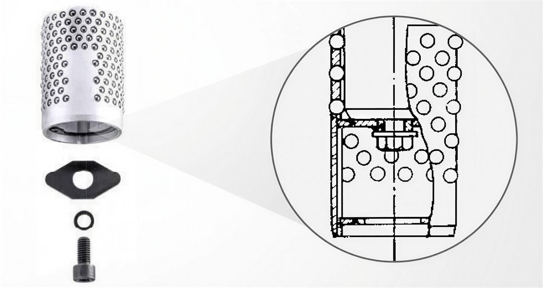
Variant with a locking device and screw (aluminum only): cage, locking plate, and fixing screw

With locking device and screw

Aluminum only. During full retraction of the bush, the locking plate holds the cage on the guide pillar. The solution for applications where the pillar and bush separate completely on each cycle.

The ball cages in three materials and their characteristics
Steinel aluminum ball cage with hardened steel balls

Aluminum

  • Lower mass than brass → lower inertia on motion reversals
  • Optimal heat resistance

Typical application: dies with frequent disassembly, tools with several guide units.
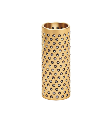
Steinel brass ball cage with hardened steel balls

Brass

  • High wear resistance and stability
  • Low ball-cage friction · optimal thermal conductivity

Typical application: optical and electronic measuring devices, high-volume production.
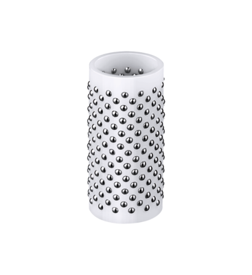
Steinel technical plastic Hostaform C (POM) ball cage with hardened steel balls

Plastic (Hostaform C)

  • Lower mass than aluminum → high-speed tools
  • High resistance to chemically aggressive media

Typical application: high cadence, environments with chemical corrosion.

06

Precision roller cages

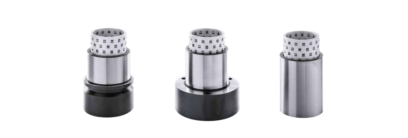
In roller guides the balls are replaced by barrel-shaped cylindrical rollers (saddle shape). The main advantage is load capacity.
6–12×
static load of a ball of the same Ø
2–3×
dynamic load of a ball of the same Ø
Cage material
Aluminum
Rollers
Hardened steel · barrel profile (saddle shape)
Movements
Longitudinal only — not rotational
Side thrust
High
Cutting clearance
Small (optimal geometric precision)
Capacity
C₁₀₀R to DIN ISO 14728-1
FIG · saddle shape rollers
Three Steinel aluminum roller cages (smooth, shoulder, flange) with the barrel-shaped cylindrical rollers arranged in an axial spiral
Design and performance
  • The rollers sit free to move in the bores and are arranged in an axial spiral, so that each roller travels its own raceway.
  • They can be used in any installation position for longitudinal movements; they do not allow rotational movement.
  • Long service life: the contact radii of the barrel profile prevent critical deformations in the corner zone — the oscillation under load is less than 0.05 µm.
  • Low mass: lower inertia forces at the reversal points and reduced cage wandering on long strokes.
  • Suitable for high side thrust and small cutting clearance: one roller withstands 6–12× (static) and 2–3× (dynamic) the load of a ball of the same Ø.
  • With optimal use, a travel speed of 40 m/min and above.
Preload and maintenance
  • Preload increases the radial stiffness of the guide but reduces ease of sliding. Excessive preload overloads the guide through an excessively high surface pressure of the rollers.
  • Recommended preload value: 2–4 µm.
  • They accept a limiting sleeve or stop to limit the cage travel on the pillar.
  • Practically maintenance-free: adequate lubrication at assembly is enough for correct long-term operation.
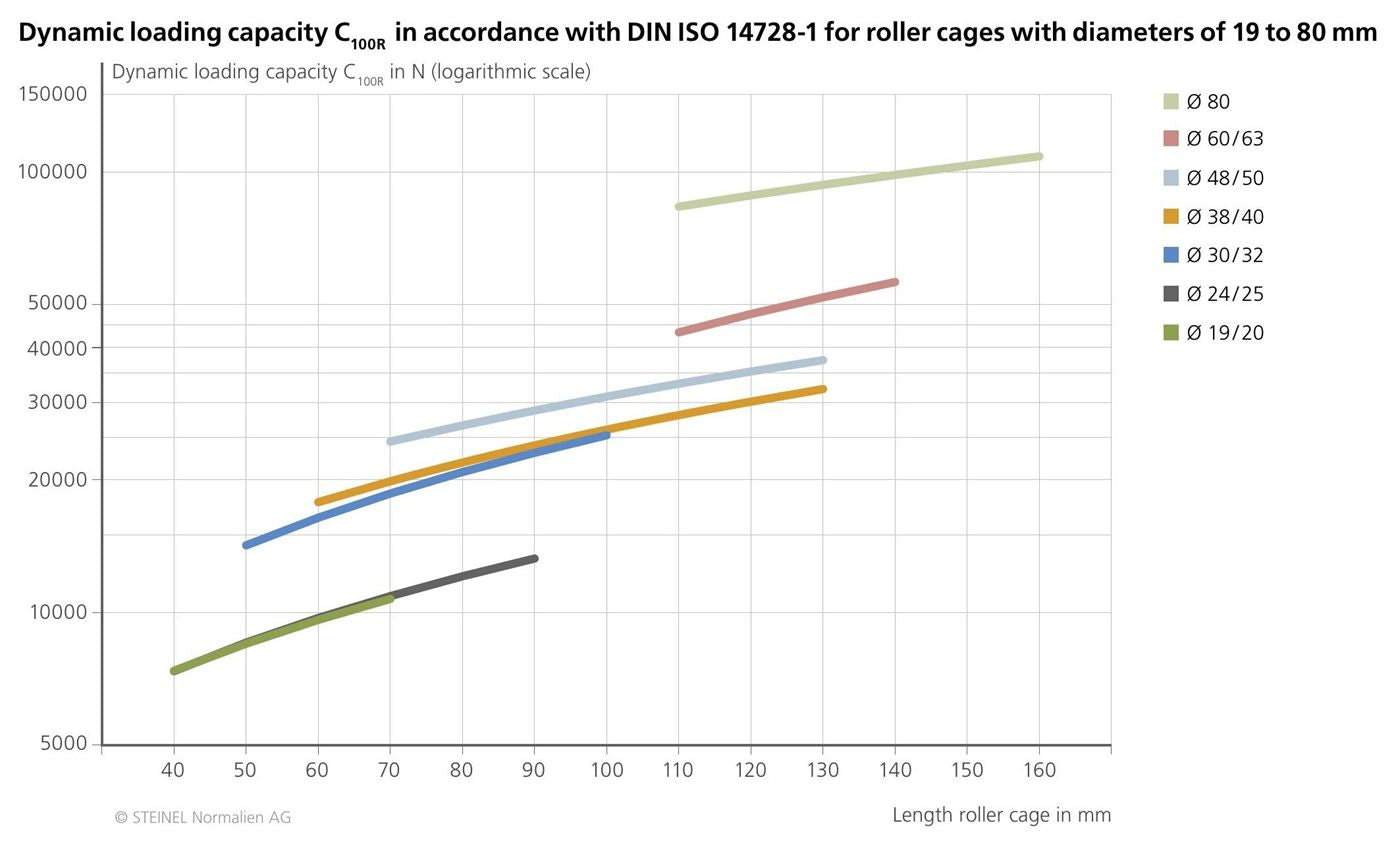
CHART · dynamic load capacity C₁₀₀R (DIN ISO 14728-1) · Ø 19–80 mm
Chart of dynamic load capacity C₁₀₀R (N, logarithmic scale) to DIN ISO 14728-1 against cage length (40–160 mm), with one curve per diameter
Fixing by mounting configuration
Recommended fixing system for each of the three bush mounting configurations (smooth, shoulder, flange).
ConfigurationFixing
SmoothGlued with Loctite 603 adhesive (Steinel ref. SZ9742). Do NOT press — pressing deforms the internal diameter. The adhesive surfaces must be free of grease.
ShoulderThe shoulder is pressed against the plate with clamps or screws.
FlangeThe flange is pressed against the plate with screws.

Additional critical rules

  • The bushes must always carry a lubricant film at assembly.
  • The die-set plates must approach parallel to each other.
  • When the rolling guides close, the rolling elements must roll, not slide.
  • Stroke/2 rule: the cage advances half the axial travel of the bush.
08

Industrial applications

Steinel Normalien guide elements are used in any application that combines a stamping press, blanking, or forming with high-precision alignment requirements.

01

Automotive

Progressive dies for body panels, drawing, and chassis and frame components.

02

Appliances and white goods

Deep drawing and cutting dies for sheet metal.

03

Electronics and connectors

High-cadence progressive dies for terminals, contacts, and housings.

04

Metal packaging

Cutting and drawing dies for cans, lids, and packaging components.

05

Precision stamping

Fine blanking — tools with very tight dimensional tolerances.

06

Die-making subcontracting

Standardized die sets with interchangeable bushes for the machine shop.

09

Frequently asked questions

01 Why can't smooth bushes be pressed in during mounting?

Smooth bushes must be glued with Loctite 603 adhesive (Steinel reference SZ9742), never pressed in. The reason is geometric: radial pressure deforms the internal diameter of the bush, which alters the nominal clearance with the pillar or the preload of the ball cage. The adhesive surfaces must be completely free of grease. Shoulder or flange bushes, by contrast, are mounted by pressing the shoulder or flange against the plate with auxiliary clamps or screws.

02 When should you choose a ball cage, roller cage, or plain guide?

The plain guide (steel/bronze or solid lubricant) accepts the highest side thrust because it distributes it over the entire bush surface, and it allows strokes as long as the pillar itself. It is the option for dies with significant side thrust. The ball cage offers the highest precision and the best speed/maintenance ratio, but its usable stroke is limited by the Stroke/2 rule and it tolerates side thrust less well. The roller cage combines high speed with load capacity (one roller withstands 6–12× the static load of a ball of the same Ø), but it only allows longitudinal movements — not rotational.

03 What load capacity does a Steinel ball cage have?

The dynamic load capacity of Steinel cages is certified as C₁₀₀B to DIN ISO 14728-1 (ball cages) and C₁₀₀R to DIN ISO 14728-1 (roller cages). The values cover diameters from 10 to 80 mm and cage lengths up to 160 mm, with detailed curves in the technical catalog for each Ø × length combination. The capacity increases with cage length and with diameter, since both parameters increase the number of balls or rollers in simultaneous contact.

04 What does the "Stroke/2" rule mean in cage sizing?

During the movement of the bush on the pillar with a ball or roller cage, the cage travels half the stroke of the bush. This means that for a total bush travel of 60 mm, the cage moves 30 mm. As a result, the usable length available for the cage must be at least (stroke / 2) + cage length + retention margins. A short cage will limit the usable stroke of the die; a cage that is too long will increase the height of the assembly without adding extra load capacity.

05 Can a pillar and bush from different ranges be combined in the same die?

To ensure the nominal clearances and preloads, it is advisable to work with a pillar and bush from the same range and series. The h3 tolerances of the pillar are designed to pair with the internal diameters of the corresponding bush — 2–7 µm clearance in the steel/bronze bush, 3–10 µm with solid lubricant, controlled preload with the ball cage. Mixing manufacturers can introduce out-of-range deviations and compromise the precision and service life of the system.

Ready to specify your guide bushes?

We distribute the complete Steinel Normalien range in Spain. We advise you on guide types, interchangeable combinations, and delivery times.