


Minimal compressed height
The closed height equals only the strip width, allowing extremely compact installations where a helical spring would not fit.
Volute springs (Buffer Springs, Puffer Federn, buffer springs or conical strip springs) are compression springs made by winding a steel strip into a conical spiral, so that the compressed height equals the width of the strip.

Conical compression springs made from a rectangular-section steel strip, coiled in a spiral around a mandrel so that each coil overlaps the next, forming a cone.
Unlike a conventional helical spring, volute springs compress to a height equal to the width of the starting strip, regardless of the number of coils or the spring's travel.
This geometry gives them a unique structural advantage: more force and travel per unit volume than any leaf spring, helical spring or torsion bar of equivalent dimensions (Floyd, Bournelis & Clark, Aerospace Mechanisms Symposium, NASA Ames, 2016).
These are the design parameters and standard manufacturing ranges. Values marked "non-standard" are assessed case by case by Surisa's engineering team.
| Parameter | Value |
|---|---|
| Construction | Rectangular-section steel strip coiled into a cone — each coil overlaps the next. |
| Standard Ø range | D: 6 – 250 mm · up to 500 mm in non-standard versions. |
| Strip thickness | From 1 mm up to ≈ 32 mm. |
| Maximum load | Up to 500 kN in large springs. |
| Spring rate | Progressive — linear in the initial phase, exponential once the coils first make contact. |
| Damping | By friction between coils in the standard version. Can be eliminated in the free-clearance version. |
| Standard material | Carbon spring steel · 50CrV · 60Si2Mn. Stainless steel on request. |
| Finishes | Phosphating · paint · nickel plating · chrome plating · dry-film lubricant. |
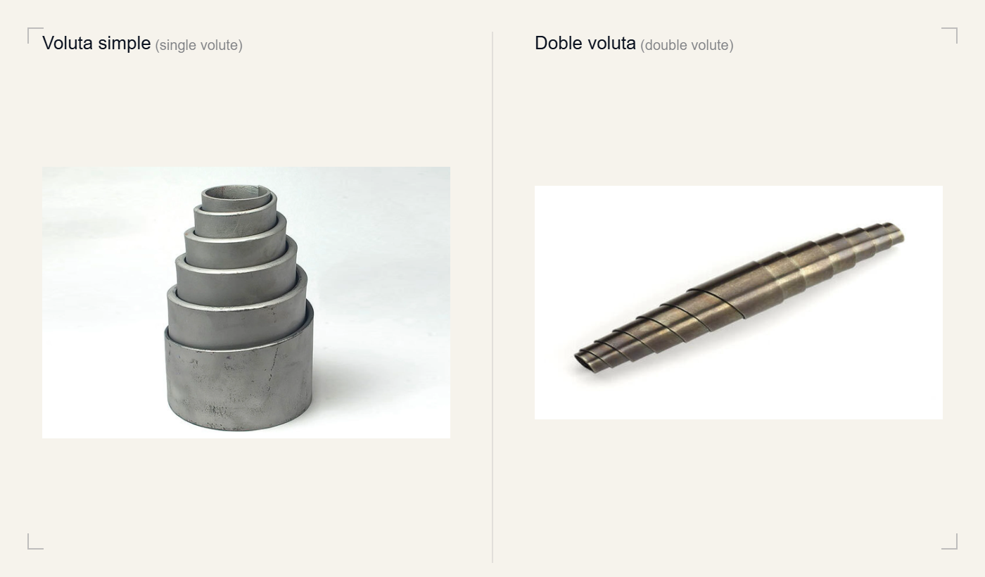
Volute springs are made in two main configurations depending on the number and arrangement of the conical spirals. Both share the same progressive characteristic curve, but their typical use differs.
A conical spiral with one larger end and one smaller end. It is the most common type in high-load industrial applications.
Two facing conical spirals forming a cylinder with the largest diameter in the centre. Common in garden shears and light cutting tools.
Tell us about your use case and our engineering team will help you choose the optimal solution.
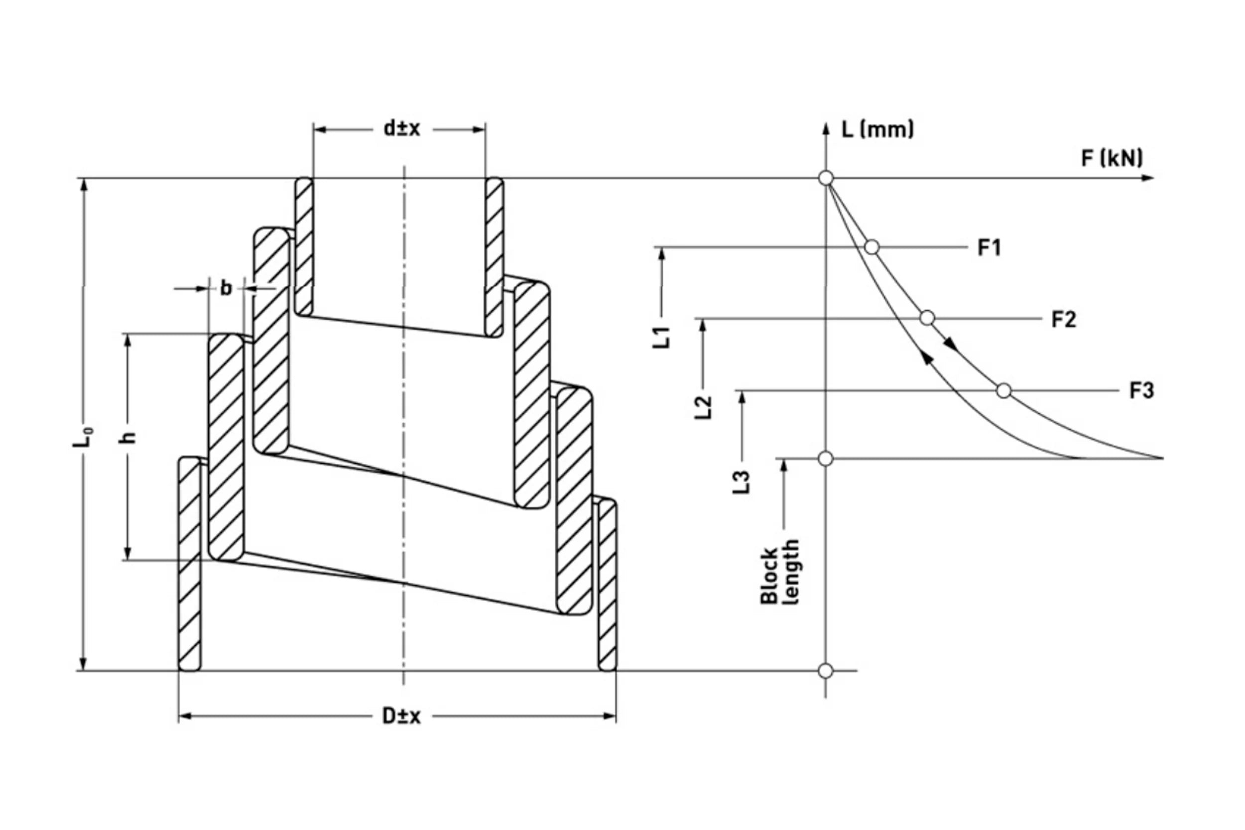
Unlike helical springs with a linear rate, volute springs show a response in two clearly distinct phases:
This progressive behaviour is especially valuable in shock absorbers: the spring reacts gently to small loads and with increasing firmness to larger ones, protecting both the machine and the workpiece.
The following set of advantages explains why, in shock-absorption applications in tight spaces, the volute spring has no direct substitute.
The closed height equals only the strip width, allowing extremely compact installations where a helical spring would not fit.
The overlap of the coils acts as an internal radial guide, preventing buckling without the need for an external guide column — a critical advantage in tight spaces.
The variable rate absorbs impacts of varying energy better than a fixed-rate spring.
More force and travel per unit volume than leaf springs, helical springs or torsion bars in the same installation space.
The conical geometry and the coil overlap provide a stability that conventional compression springs cannot match.
Their compact profile and progressive response have no direct equivalent, so they find use across very diverse sectors — from tooling to satellite deployments.
A stop and damping element in cutting, bending and forming dies. They absorb the press's end-of-stroke impact, protecting the tooling.
The first railway buffer device using a volute spring was patented by John Brown in 1848. They remain a standard component in buffer assemblies between wagons today, thanks to their high energy absorption in a small space.
The suspension system of the M4 Sherman tank used volute springs as its main suspension element. They are also used in horizontal and vertical suspensions of industrial vehicles.
Damping of abrupt movements at end stops, feeding systems and industrial handling.
The double volute is a common component of garden shears and pruners, where self-guiding and compactness are decisive.
Lockheed Martin used volute springs in the Launch Restraint Assemblies (LRA) of satellite deployments. Testing validated force-output stability after 10 thermal cycles between −100 °C and +95 °C and under random-vibration environments (Floyd et al., NASA AMS 2016).
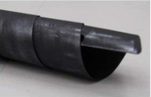
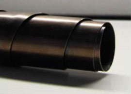
The configuration of the spring's ends has a direct impact on deployment behaviour and stability. For high-precision or aerospace applications, it is always advisable to specify closed ends with a dead coil on each side on the engineering drawing. That said, three variants can be distinguished:
| Configuration | Characteristics | Recommendation |
|---|---|---|
| Unaltered ends unaltered |
Rectangular tips on the inner/outer coil. Causes unstable deployment and high exponential friction as it approaches solid height. | Not recommended |
| Ground ends ground |
Removes the rectangular tips. Improves deployment stability, but friction build-up persists on the inner coil. | Limited use |
| Closed ends closed · dead coil |
A dead coil at each end. Stable deployment, no friction changes throughout the travel, reliable force measurement. | Recommended |
General industrial use
Corrosion · food · chemical
A volute spring is a conical compression spring made from a steel strip coiled in a spiral, where each coil overlaps the next. Its fundamental difference from the helical spring is the compressed height: the volute spring compresses to the strip width (regardless of the number of coils), whereas the helical spring compresses to the number of coils multiplied by the wire diameter. This makes it possible to fit more travel and more force into a minimal axial space.
As it compresses, the coils come into contact in sequence, starting with the largest-diameter coil (the least stiff). Each coil that touches the support plane stops being active, reducing the spring's active length and increasing its rate. The result is a load-deflection curve that goes from linear to exponential from the first coil contact (initial bottoming load), which makes the spring an ideal progressive absorber for impacts of varying energy.
Volute springs are common in stamping dies and press tooling, railway buffers (in use since 1848), suspensions of industrial and military vehicles, end stops in automation, garden tools and, in custom versions, in satellite deployment systems and aerospace components where a minimal compressed profile is a design requirement.
The standard version generates friction between coils as it compresses, which is useful for damping vibration but ill-suited to continuous high-frequency dynamic cycling (the accumulated friction artificially raises the measured force and causes premature wear). If the application involves repeated cyclic compression and extension, request the version with free space between coils, which eliminates contact and allows dynamic operation without friction or heat build-up.
To size or select a volute spring you need to know: external diameter (D), internal diameter (d), strip width (h), strip thickness (b), free height (L₀), required load and working stroke. With this data and the expected load curve, Surisa's engineers can recommend the right catalogue reference or work out the manufacture of a custom spring.
Standard volute springs are made from carbon spring steel (50CrV, 60Si2Mn). For applications with corrosion requirements, high temperature (above 180 °C), humid environments or vacuum, Surisa offers stainless steel versions and special finishes (dry-film lubricant, nickel plating). Contact the engineering team to assess the most suitable material for each specific application.
Tell us about your use case and our engineering team will help you choose the optimal solution.