


— Type
Open-pitch helical spring that resists an axial load.
Helical open-pitch springs that resist an axial load: as they compress they store energy and return it as return force.
They are the most widely used type of spring in industry. Their behaviour is tuned by combining a handful of geometric and material parameters.
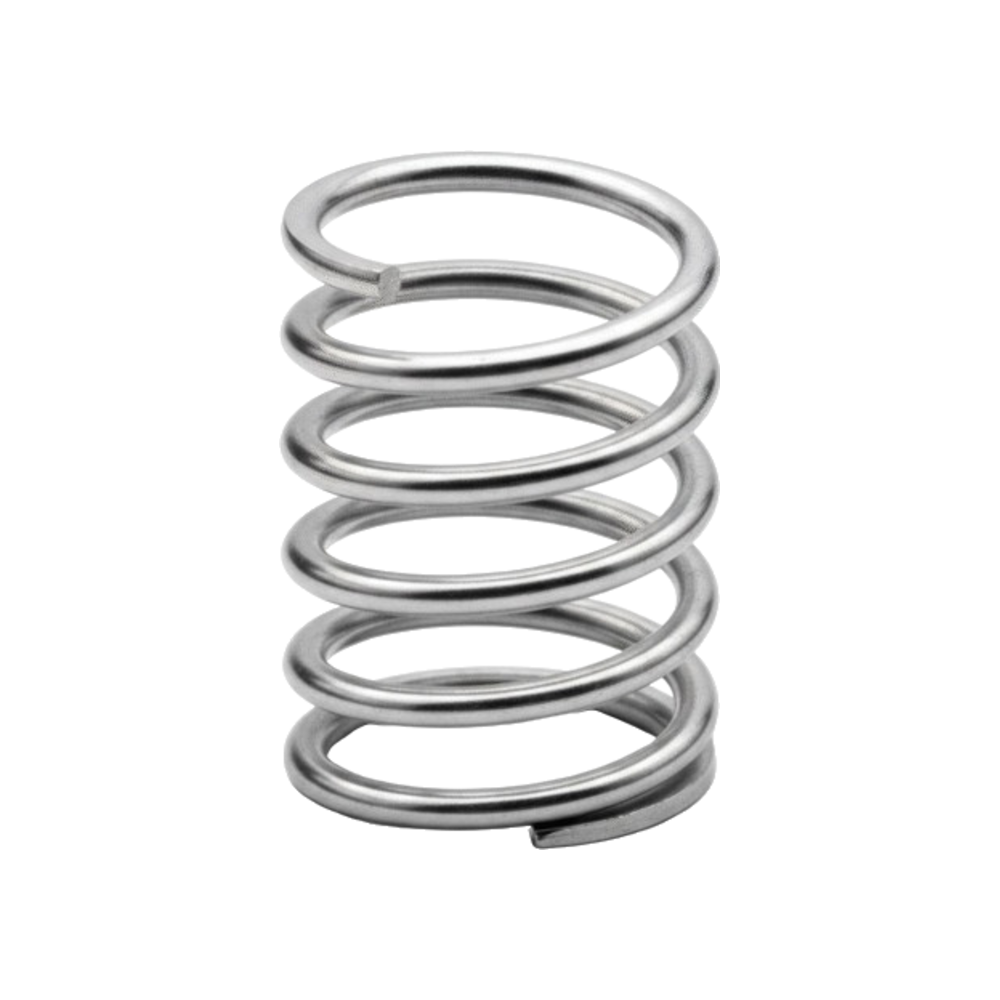
Compression springs, known as compression springs in international technical terminology, are open-pitch helical springs designed to resist an axial force. When a load is applied that tends to shorten them, the coils store energy and, once the load is removed, the spring recovers its length by exerting a return force.
They are the most common type of spring in industry: they are found in all kinds of mechanisms, from a ballpoint pen to heavy machinery, valves, automotive, household appliances and tooling.
Their versatility comes from the fact that load, travel and stiffness are tuned by combining a handful of geometric and material parameters. The same spring family covers anything from the minimal forces of an electrical contact to the high loads of a suspension or die set.
Open-pitch helical spring that resists an axial load.
Round (square section in high-frequency applications).
Approximately linear: F = k · x (load proportional to deflection).
k = (G·d⁴) / (8·Dm³·Na), where G is the shear modulus.
C = Dm / d · practical range 4–12, ideal 6–10.
Closed and ground · closed · open · open ground.
Carbon steel · stainless 302 / 316 / 17-7 PH · chrome-Si/V · bronze.
Standardized series or fully custom to drawing.
The behaviour of a compression spring is defined by a set of interrelated parameters. Selecting them in practice combines the available housing with the force required at the working point.
| Parameter | Symbol | Influence |
|---|---|---|
| Wire diameter | d | The most influential: stiffness varies with the 4th power of the diameter. |
| Mean coil diameter | Dm | The larger the diameter, the lower the stiffness. |
| Number of active coils | Na | More active coils mean lower stiffness and greater travel. |
| Spring rate | k = F/x | Force required per unit of deflection. |
| Spring index | C = Dm/d | Governs manufacturability; practical range 4–12, ideal 6–10. |
| Free / solid length | L₀ / Lc | Length under no load / with the coils fully in contact. |
The basic dimensions that define a compression spring: wire diameter (Ø d), external diameter (De) and mean diameter (Dm), free length (L₀), pitch (p) and number of active coils (Na).
k = (G·d⁴) / (8·Dm³·Na)
The force-travel curve is approximately linear (F = k · x). Since stiffness depends on d⁴, a 1% error in the wire diameter alters stiffness by about 8%: wire tolerance is critical.
The spring index (C = Dm/d) governs manufacturing: below 4 the coils are hard to wind; above 12 the spring tends to buckle and tangle. The ideal range is between 6 and 10.
The slope of the line is the spring rate k. As the wire diameter increases (Ø d·1,2) the line steepens: stiffness grows with the 4th power of the diameter.
The type of end determines how the spring seats, how the load is distributed and whether it needs guiding. It results from combining two independent decisions: the pitch of the end coils and the finish of the bearing face.
Closed: the pitch of the last coils is reduced until the end coil touches the previous one, creating a stable base. Open: the pitch stays constant up to the tip — lower solid height, but it requires preload.
Ground: the end face is machined flat and perpendicular to the axis, with a continuous bearing surface (270°–330°). Unground: the spring bears on the round edge of the wire, with contact at fewer points — more economical.
Economical; common in fine wires and general use.
Maximum squareness and seating; precision and long fatigue life.
Lower solid height, greater travel; requires preload.
Low solid height with a flat bearing surface.
For precise loads and long fatigue life, closed and ground is specified: it offers the best squareness (within 3° in the free position) and the least buckling, at the cost of additional machining. For very fine wires or undemanding loads, closed unground is sufficient and more economical.
Tell us the load, working length, deflection, available diameters and service environment — and our engineering team will help you size the optimal compression spring. Manufacturer since 1975.
Buckling is the risk of a slender spring flexing sideways when compressed. As a rule of thumb, it appears when the free length exceeds about 4 times the mean diameter. To prevent it:
Guide the spring
On a shaft or inside a tube (with lubrication to reduce friction).
Closed and ground ends
They improve squareness and seating, reducing the tendency to buckle.
Profiles with greater lateral stability
Conical or barrel when space and slenderness demand it.
In high-frequency dynamic applications it is also worth watching for resonance (surge): it is mitigated with variable pitch on some coils, nested springs (one inside another) or square-section wire.
A slender spring without guiding flexes sideways (left); guided on a shaft, it stays straight under load (right).
Compression springs are manufactured in a wide range of materials according to load, environment and working cycles. For humid, marine or food-processing environments, stainless steel (302, 316, 17-7 PH) is the usual choice; for high stresses and demanding cycles, chrome-silicon and chrome-vanadium alloys offer the best fatigue behaviour.
| Material | Designation | Application |
|---|---|---|
| Music wire | ASTM A228 | High strength, dry environments; best cost-performance ratio |
| Hard drawn steel | ASTM A227 | General use, static loads |
| Oil tempered steel | ASTM A229 | Medium and dynamic loads |
| Chrome-silicon steel | ASTM A401 | High stress, temperature and shock |
| Chrome-vanadium steel | ASTM A231 | Fatigue and impact |
| Stainless steel 302 / 316 / 17-7 PH | — | Corrosion, marine and food environments |
| Phosphor bronze / beryllium copper | — | Electrical conductivity, corrosive environments |
As the most versatile spring, the compression spring appears in practically every industry. To size it —load at a given working length, deflection, available diameters, material and end type—, Surisa's technical team, a specialized manufacturer since 1975, offers free engineering support.
Valves, clutches, damping and suspension.
Return and preload in hydraulic and pneumatic systems.
Push-buttons, contacts and return mechanisms.
Ejectors, hold-downs and returns in moulds and dies.
Ballpoint pens, latches and dispensers.
A compression spring is an open-pitch helical spring that resists an axial load: when compressed, the coils store energy and, once the load is removed, it recovers its length by exerting a return force. It is the most common type of spring in industry. Its behaviour is defined by the spring rate (k = F/x), which indicates the force required per unit of deflection.
On four main factors: the wire diameter (the most influential, since stiffness varies with the fourth power of the diameter), the mean coil diameter, the number of active coils and the material modulus. The relationship is k = (G·d⁴)/(8·Dm³·Na). That is why a small error in the wire diameter changes stiffness so much: a 1% deviation in the wire alters the rate by about 8%.
The main ones are: closed and ground (maximum squareness and seating, ideal for precision and high fatigue), closed unground (economical, general use and fine wires), open (lower solid height, requires preload) and open ground (specific cases of low height with a flat bearing). The type of end affects the free length, the solid height and the number of active coils, so it also influences the force. For precise loads, the usual choice is closed and ground.
Buckling (sideways flexing under load) usually appears when the free length exceeds about 4 times the mean diameter. It is prevented by guiding the spring on a shaft or inside a tube, using closed and ground ends to improve squareness, or choosing profiles with greater lateral stability (conical or barrel) when the spring is very slender. In dynamic applications it is also advisable to control resonance.
Music wire (ASTM A228) for dry environments and the best cost-performance ratio, hard drawn or oil tempered steel for general use and dynamic loads, chrome-silicon and chrome-vanadium for high stress and fatigue, and stainless steel (302, 316, 17-7 PH) for corrosion, marine or food environments. For electrical conductivity, phosphor bronze or beryllium copper are used. The choice depends on the load, temperature, corrosion and number of cycles.
Send us the load, working length, deflection, available diameters, material and end type — and we'll get back to you with the optimal compression spring, standard or fully custom. Free engineering support, manufacturer since 1975.