


— Ranges · intermediate series
The green, blue, red and yellow series cover Dh = 10 — 63 mm and L₀ = 25 — 305 mm.
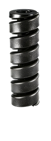
Helical compression springs made from rectangular-section profiled wire in 52SiCrNi5 (DIN 1.7117) steel, identified by colour coding to the ISO 10243:2019 standard. Surisa distributes all eight series — green, blue, red and yellow (interchangeable intermediate series) plus lilac, gold, black and double black — with forces up to 45,000 N (4,500 daN), and offers free technical support from specialist engineers for die work, moulds and industrial machinery.
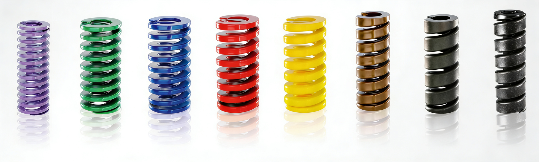
Helical compression springs built from rectangular-section profiled wire. They are identified by a colour code indicating the load level, which lets you select the right series visually without consulting tables.
The ISO 10243:2019 — «Tools for pressing — Compression springs with rectangular section — Housing dimensions and colour coding» standard governs the four intermediate series (green, blue, red and yellow): it sets the housing dimensions (Dh and Dd) and the colour code associated with each force level. Two springs of the same size but different colour are interchangeable without altering the die design.
In international technical terminology they are called die springs, ISO 10243 springs or rectangular wire compression springs. They are the benchmark standard in stamping, die work, injection moulds, hydraulic systems and industrial machinery wherever high force is required in a compact space and a service life rated for millions of cycles.
Surisa distributes and keeps permanent stock of all eight series of helical springs in the system, with free technical support on selection. The four intermediate series (green, blue, red and yellow) are standardised by ISO 10243 and are dimensionally interchangeable; the remaining four extend the force range downwards (lilac) and upwards (gold, black and double black) while keeping compatibility with the housing system.
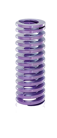
Low loads · spaces where the nominal force can be very small.
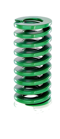
Versatile springs · long life with good travel.
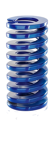
Most widespread application · force-travel balance.
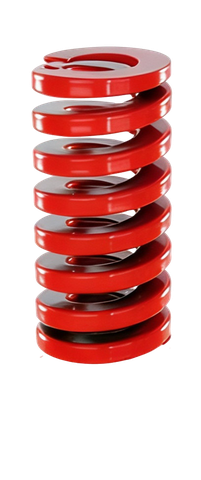
Medium-high forces · contained travel.
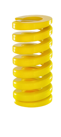
High force · reduced travel · industrial preload.
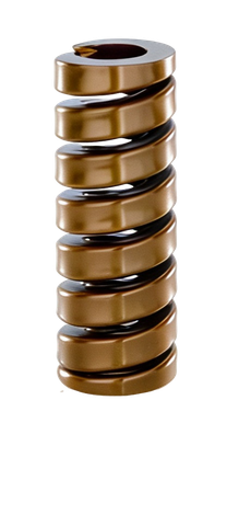
Intense preload · long life only with short strokes.
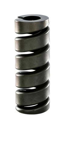
Permanent preload · very short travel.
Up to 45,000 N (4,500 daN) · extreme loads.
| Series | Colour | Load level | EN designation | Standard | Long life s₁ | Maximum s₂ |
|---|---|---|---|---|---|---|
| SZ-8005 | Lilac | Extra light | extra light load | — | 35 % | 50 % |
| SZ-8010 | Green | Light | light load | ISO 10243 | 30 % | 40 % |
| SZ-8020 | Blue | Medium | medium load | ISO 10243 | 25 % | 37.5 % |
| SZ-8030 | Red | Strong | heavy load | ISO 10243 | 20 % | 30 % |
| SZ-8040 | Yellow | Very strong | very heavy load | ISO 10243 | 17 % | 25 % |
| SZ-8045 | Gold | Extra strong | extra heavy load | — | 10 % | 15 % |
| SZ-8047 | Black | Extra strong, no travel | extra heavy load (no s₁/s₂) | — | s_max only | F_max only |
| SZ-8049 | Double black | Double extra strong | double, extra, extra heavy load | — | s_max only | F_max only |
The higher the load, the lower the permissible deflection percentage. The SZ-8047 and SZ-8049 series are so stiff that their technical tables are specified solely with s_max and F_max: they are designed for permanent preload with very short travel.
The green, blue, red and yellow series cover Dh = 10 — 63 mm and L₀ = 25 — 305 mm.
The SZ-8047 and SZ-8049 series extend the range up to Dh = 50 mm and L₀ up to 200 mm with short travel.
All series share the same material, treatments and manufacturing process. The differences lie in the wire section and the coil geometry, which determine the load level and the permissible deflection percentage.
| Material | 52SiCrNi5 (DIN 1.7117) alloyed valve-spring steel |
| EN designation | Profiled valve spring steel wire |
| Wire section | Profiled rectangular |
| Spring type | Helical compression · helical compression spring |
| Heat treatment | Hardened and tempered |
| Surface treatment | Shot peening (stress shot peening) |
| Pre-setting | Controlled flattening · stabilises the F/s curve |
| Finish | Powder coating in the identifying colour |
| Ends | Closed and ground (closed and rectangular ground) |
| Working temperature | −30 °C to +180 °C |
| Maximum force | Up to 45,000 N (4,500 daN) — SZ-8049 series |
| L₀ tolerance | ±1 %, minimum ±0.75 mm |
The combination of 52SiCrNi5, heat treatment, shot peening and pre-setting is the standardised recipe for fatigue-rated springs.
Introduces residual compressive stresses at the surface that delay crack nucleation.
Eliminates the initial force loss caused by relaxation. The force exerted in operation matches the theoretical curve from the very first cycle.
Tell us about your use case and our engineering team will help you choose the optimal solution.
A spring is selected per ISO 10243 by the available housing (Dh and Dd) and by the force required at the working point. The standardised parameters are as follows.
| Dimension | Meaning | Tolerance |
|---|---|---|
| L₀ | Free length of the spring under no load (mm) | ±1 %, minimum ±0.75 mm |
| Dh | External diameter of the spring / outer guide sleeve (mm) | H15 |
| Dd | Internal diameter / inner guide shaft · pin (mm) | h15 |
| s₁ | Working travel for long life (% of L₀) | per series |
| s₂ | Maximum permissible travel (% of L₀) | per series |
| F₁ | Force in N at point s₁ | calculated from c and s₁ |
| F₂ | Force in N at point s₂ | calculated from c and s₂ |
| c | Spring rate (N/mm) | ±10 % |
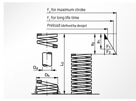
F(s) · The manufacturer's general recommendation is always to size the spring for the long-life travel (s₁). The maximum travel (s₂) is intended for exceptional situations, not for continuous operation.
5 · 6.3 · 8 · 10 · 12.5 · 16 · 20 · 25 · 32
Covers practically any standard European die housing. Dh and Dd are standardised for the four intermediate series (SZ-8010 to SZ-8040), ensuring interchange between load levels without modifying the housing.
The force-travel curve of the helical spring is approximately linear (F = c · s) until it approaches the maximum travel. Practical selection is done by identifying three points on the curve.
The service life of a helical spring depends as much on the choice of series as on the assembly conditions. Applying these six rules significantly extends the number of cycles before fatigue and reduces the likelihood of premature failure.
The greater the free length L₀, the lower the deflection percentage and the higher the number of cycles before fatigue for the same absolute stroke.
A blue spring (medium) working at 25 % of L₀ lasts much longer than a yellow one (very strong) working at the same percentage.
Preload eliminates the initial non-linear range and stabilises the force exerted in operation.
Exceeding s₂ drastically reduces service life even if the part does not break immediately.
Check that the total does not exceed the maximum permissible deflection for the series. The most common cause of premature failure.
By means of an inner shaft (Dd) or outer sleeve (Dh). In long springs (L₀ > 4·Dh) guiding is essential to prevent buckling.
Preload + working stroke > maximum permissible deflection. Always check the sum before ordering a reference.
Spring as long as possible, series as light as possible that covers the required force.
ISO 10243 helical springs are the benchmark standard in any application requiring high force in a compact space with a service life rated for industrial production.
Sheet and part extraction in progressive dies, sheet clamping in deep drawing, and return of elements in cutting and forming dies. The benchmark application of the ISO 10243 system.
Part ejection, ejector-plate return, slide closing and core return. Service life rated for millions of cycles.
Clutches, brakes, safety valves and return systems in hydraulic and pneumatic actuators. High force in a compact space.
Mould closing, injection systems and vulcanisation presses. Resistance to continuous service and to the process temperature.
Impact damping and return systems in cutting and forming tools. Robustness against dust and vibration.
Direct replacement of original springs in existing dies thanks to ISO 10243 dimensional interchangeability, without redesigning the housing.
For applications outside the standard catalogue, custom-manufactured special sizes, or advice on the optimal load-travel combination for a specific die, the Surisa engineering team handles enquiries free of charge.
ISO 10243:2019 is the international standard «Tools for pressing — Compression springs with rectangular section — Housing dimensions and colour coding», which sets the housing dimensions (inner guide shaft diameter Dd and outer guide sleeve diameter Dh) and the colour coding for rectangular-section compression springs used in dies. The standard covers the four intermediate series: green (light load), blue (medium), red (strong) and yellow (very strong). The extra-light series (lilac) and the super-strong ones (gold, black and double black) are not within ISO 10243, although they share the same housing dimensions to maintain interchangeability with the rest of the system.
Yes. That is precisely the purpose of ISO 10243: the four series green, blue, red and yellow are dimensionally interchangeable — they share Dh, Dd and standard lengths — which lets you change the load level without modifying the die. The force exerted and the maximum deflection percentage do change: you must recalculate the working stroke and the preload when moving to a stronger series so as not to exceed the maximum recommended deflection of the new series (40 % for green, 25 % for yellow).
A rectangular-wire helical spring offers long strokes with medium-high force (from a few millimetres to several centimetres of travel) and is fitted as a single piece. A DIN 2093 disc spring offers very high forces with short travel and can be combined in series/parallel stacks to tune the force-displacement curve. For sheet extraction, ejector-plate return and similar applications, the helical spring is the usual choice; for intense axial preload in very little space, the disc spring.
The force depends on the series, the diameter and the length. As a reference, the intermediate series (green to yellow) cover typical forces between 100 N and 7,000 N. The SZ-8045 series (gold) reaches around 15,000 N; the SZ-8047 (black), up to 20,000 N; and the SZ-8049 (double black), up to 45,000 N (4,500 daN) at maximum travel. For higher forces, disc spring stacks or specific solutions on request are used.
52SiCrNi5 steel with heat treatment, shot peening and pre-setting allows continuous operation between −30 °C and +180 °C without significant loss of elastic properties. For temperatures above 180 °C it is necessary to use special springs in high-temperature alloy steels or nickel alloys; Surisa can supply these variants on request and offers free technical support on selecting the right material.
The most common causes are three: total deflection (preload + stroke) above the maximum recommended for the series, lack of guiding that produces buckling or misalignment, and selecting a series that is too strong working at an inappropriate deflection percentage. The practical rule is: spring as long as possible, series as light as possible that covers the required force, and minimum preload of 5 % or 2 mm to stabilise the force-displacement curve.
Yes. In addition to the standard catalogue in the eight colour series, Surisa can custom-manufacture helical springs with special sizes, in stainless steels for corrosive environments and in special alloys for high temperature or aggressive chemical environments. The Surisa engineering team advises free of charge on the feasibility of each case and the delivery times.
Tell us about your use case and our engineering team will help you choose the optimal solution.