FIG · plain and slotted
Plain and slotted disc spring for ball bearing preload — Surisa
Thickness
proportionally reduced
F/s curve
regressive · flat zone
Function
preload + thermal compensation
01

What are ball bearing disc springs?

Conical elastic washers fitted alongside ball bearings to retain them, providing an elastic support that absorbs vibration and eliminates the noise caused by spinning without axial load.

The disc spring also acts as a compensator for the thermal expansion produced by the heating and cooling of the shaft on which the bearing is mounted, significantly increasing bearing service life.

Its key advantage is the minimal force variation across a wide range of its travel: the spring supplies the force needed for correct axial retention and keeps it within a suitable range, without overloading or loosening the bearing.

02

Types of ball bearing disc spring: plain and slotted

There are two types of ball bearing disc spring. Both share the same operating principle — working in the regressive zone of their characteristic curve — but they differ in the level of preload force and in how finely they behave.

plain

Plain

A conical elastic washer whose force vs. deflection curve is regressive, allowing force variation to stay low relative to its deflection.

slotted

Slotted

A variant of the above with slots on the inner circumference. It delivers an even lower preload force and the minimum force variation for the greatest deflection. Suited to small-sized bearings.

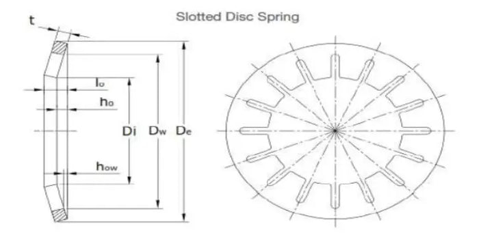
FIG · slotted disc spring — nomenclature
Slotted disc spring with nomenclature: thickness (t), internal diameter (Di), external diameter (De), maximum deflection (h₀)
t
thickness
Di
internal Ø
De
external Ø
hₒ
max. deflection
03

Axial preload in bearings

Axial preload is the internal load applied to a bearing when the system is at rest. Managing it correctly directly determines the service life, noise and stiffness of the assembly.

The ball bearing disc spring solves this problem because it works in the flat zone of its load-deflection curve: small dimensional changes due to temperature or wear barely alter the force exerted. The engineer designs for a stable preload, not for a rigid geometry.

Insufficient preload
  • · Slippage between rolling elements and race → premature wear and noise
  • · Reduced shaft stiffness → loss of precision in spindles and transmission shafts
  • · Vibration at the bearing's characteristic frequencies
Excessive preload
  • · Heating from excessive friction
  • · Drastic reduction of the bearing's L10 life
  • · Risk of seizure under high-temperature conditions

Let's talk about your project

Tell us about your use case and our engineering team will help you choose the optimal solution.

04

The regressive curve · differential behaviour

Unlike a conventional helical spring (linear behaviour), the ball bearing disc spring works in the regressive zone of its characteristic curve, where stiffness decreases with deflection.

In the designed working zone (typically between 75% and 100% of total deflection), the ΔF/Δs ratio is very low:

  • A dimensional change of ±0.05 mm from thermal expansion produces a minimal force variation.
  • The bearing stays correctly loaded throughout the machine's entire thermal cycle.
  • There is no need to adjust the preload with operating temperature.

This behaviour is impossible to achieve with a rigid spacer or an adjusting nut, which fix the position but not the force.

Note for the designer

The regressive zone appears when the h/t ratio (free cone height over disc thickness) exceeds a value of around 1.41. Ball bearing disc springs are specifically designed to work in this zone.

FIG · F vs. s curve — comparison
Force vs. deflection curve — ball bearing disc spring compared with a helical spring Comparison of force-deflection curves. The disc spring shows regressive behaviour with a flat zone between 75% and 100% of deflection, where force variation under small dimensional changes is minimal. The helical spring shows linear behaviour: force grows in proportion to displacement. The shaded zone indicates the optimal working range for bearing preload applications. F [N] s [mm] helical disc spring regressive zone · 75–100% s
Disc spring
Regressive behaviour · flat zone between 75–100% of deflection.
Helical
Linear behaviour · force grows in proportion to displacement.
05

Thermal expansion compensation

In most industrial applications, the shaft and the housing have similar but not identical thermal expansion coefficients, and the thermal mass of each component means they heat up and cool down at different rates. The result is axial dimensional changes of tenths of a millimetre that, on a rigid preload system, can generate load variations of hundreds of Newtons.

With a well-selected ball bearing disc spring, those 0.138 mm of dimensional change produce a force variation below 10–15% of the nominal preload. With a rigid system, the same expansion can generate a preload increase of several kN, with a risk of overloading the bearing.

Indicative calculation · axial expansion
Indicative calculation of axial shaft expansion under typical industrial thermal conditions
Parameter Value
Shaft material (42CrMo4 steel) α = 11.5 × 10⁻⁶ /°C
Length between supports 300 mm
Temperature variation ΔT = 40 °C
Resulting axial expansion Δl ≈ 0.138 mm
Δl = L · α · ΔT = 300 × 11.5×10⁻⁶ × 40 ≈ 0.138 mm
06

Typical industrial applications

Ball bearing disc springs are found in equipment where the combination of precision, variable temperature and long service life is a design requirement.

01

Machine tools and CNC spindles

> 10,000 rpm · tandem angular contact bearings

High-speed spindles are extremely sensitive to preload variations. Precision spindle manufacturers use disc springs for tandem angular contact bearings, where the preload must remain constant from cold to operating temperature. The alternative — manual adjustment with a nut — requires periodic recalibration and is a source of machining errors.

02

Electric motors

Standard in IE3 / IE4 motors

In induction motors and servomotors, the free-end bearing (non-drive side) works with an axially floating support. The disc spring in the motor end cover provides the minimum preload needed to prevent race skidding without restricting the axial expansion of the rotor shaft.

03

Rotary pumps and compressors

Centrifugal · screw · thrust

Centrifugal pumps and screw compressors generate axial loads that vary with flow rate and pressure. The disc spring acts as a preload element that ensures contact in the thrust bearing even under light-load conditions (start-up, no-load operation).

04

Precision gearboxes

Helical gears · angular contact

In helical gear reducers, the axial component of the meshing force must be absorbed by thrust or angular contact bearings. A disc spring on the shaft's floating support ensures this bearing stays loaded across the entire operating range, preventing skidding (slippage of the rolling elements).

05

Railway and traction equipment

−40 °C to +80 °C · special alloys

Bogies and traction axles work under extreme temperature conditions (from −40 °C to +80 °C) and require materials and designs that maintain function across that whole range. In these applications, special alloys are often used (see the materials section).

07

Stacking in parallel

When an application requires a greater force than a single washer can provide, stacking in parallel is possible: the spring force increases in proportion to the number of springs used. The hysteresis caused by friction between the pieces will have an effect on the force vs. deflection curve.

When to stack in parallel?

When the available axial space does not allow scaling up to a larger-diameter spring, or when a force greater than the catalogue offering is needed for the external diameter constrained by the bearing.

Rule of thumb

With 2 springs in parallel, the force doubles while keeping the deflection. With 3, it triples. The useful working travel does not change, but the hysteresis increases.

Practical limitation

For high-precision applications (machining spindles, instrumentation), stacking more than 2 pieces in parallel can introduce unacceptable force hysteresis. In these cases we recommend selecting a larger-diameter spring or a different h/t ratio. Consult our engineers.

single piece
Ftotal
1·F
stotal
1·s
×1
2 in parallel
Ftotal
2·F
stotal
1·s
×2
3 in parallel · hysteresis ↑
Ftotal
3·F
stotal
1·s
×3
08

Materials

Ball bearing disc springs are made from high-quality spring steel. They can also be made from other materials to offer resistance to corrosion, to high or low temperatures, or for applications that require a non-magnetic material.

For this, stainless steels and alloys such as Inconel or Nimonic 90 are used. As these steels have a different modulus of elasticity, the spring calculation will change and, in some cases, the pieces must be made with a different thickness to meet the specifications of the original spring.

Recommendation

For applications with an operating temperature above 200 °C or in corrosive environments, material selection is critical to the spring's service life. Consult us before specifying.

Materials available for ball bearing disc springs, with their standard, maximum continuous temperature, corrosion resistance and magnetic behaviour
Material Standard · designation Max. continuous temp. Corrosion resist. Magnetic Typical application
Spring steel 51CrV4 / DIN 17221 ~200 °C Low (coating) Yes General industrial use
Stainless steel 1.4310 (AISI 301) ~300 °C High Weak Food, chemical, marine
Stainless steel 1.4568 (17-7 PH) ~350 °C High Weak Aerospace, high strength
Inconel 718 UNS N07718 ~650 °C Very high No High temperature, aerospace
Nimonic 90 UNS N07090 ~850 °C Very high No Turbines, cryogenic
09

Selection guide · key parameters

Selecting a ball bearing disc spring requires determining the following starting parameters. With this data, our team can recommend the most suitable catalogue model or calculate a special piece if the standard does not meet the requirements.

De Maximum available external diameter
Constrained by the bearing's external diameter and the housing. It limits the diameter of the selectable spring.
Di Minimum internal diameter
Constrained by the diameter of the shaft or the mounting sleeve.
F Required preload force [N]
From the bearing manufacturer's catalogue (light, medium or heavy) or calculated according to the system loads.
s Working travel
Expected axial dimensional change — thermal expansion plus wear accumulated over service life.
T Operating temperature
Determines the choice of material and any coatings.
Ω Environment
Humidity, corrosive agents, metallic dust, lubricants. Defines the need for coatings or special steels.
10

Frequently asked questions

01 Can I use a DIN 2093 spring instead of one specifically made for bearings?

Technically it is possible if the dimensions and force curve are compatible. However, ball bearing disc springs are specifically designed to work in the regressive zone of their curve, with h/t ratios optimised for this purpose. A standard DIN 2093 spring may behave more linearly, which is not optimal for bearing preload applications. Consult us.

02 How does the lubricant affect the force curve?

Lubrication reduces the spring's hysteresis. Under dry conditions, friction between stacked springs (in parallel) increases hysteresis and can produce differences of up to 20–30% between the loading and unloading curves. With lubricant (grease or oil), this difference is significantly reduced. For high-precision applications, always specifying lubrication is recommended.

03 What is the expected service life of a ball bearing disc spring?

In static or quasi-static preload applications (a bearing with few load reversals per day), the practical service life is indefinite if the working stress does not exceed the material's fatigue limits. In dynamic applications (continuous vibration, frequent load cycles), service life depends on the deflection amplitude and must be calculated according to the criteria of DIN 2093 / DIN EN 16983.

04 Which coating do you recommend for environments with a risk of corrosion?

For humid environments or mild corrosion: phosphating + oil or zinc chromate. For marine or acidic environments: 1.4310 stainless steel or zinc-nickel coating. For extreme cases: Inconel or Nimonic with no additional coating.

Let's talk about your project

Tell us about your use case and our engineering team will help you choose the optimal solution.