


High-force springs
Nearly linear curve.
Manufacturing and quality specifications for disc springs: dimensions, approved materials, processes by thickness, tolerances, and behavior under relaxation and fatigue.
The standard classifies the parts into three groups by thickness (Group 1: < 1.25 mm · Group 2: 1.25 — 6 mm · Group 3: > 6 mm up to 14 mm) and into three series by the h₀/t ratio (Series A, B and C), which defines the shape of the force-deflection curve.
DIN 2093 is the historic German designation; DIN EN 16983 is its harmonized European version. Both are used interchangeably. The companion standard DIN 2092 / DIN EN 16984 covers the calculation methods.

The standard applies to disc springs —conical washers with elastic properties— designed to generate an axial force under compression. The parts it covers are intended for both static applications (permanent preload) and dynamic applications (repeated load and unload cycles).
This sets it apart from standards such as DIN 6796, which covers conical washers intended exclusively for static load in bolted joints.
The standard establishes three groups based on the material thickness (t). Thickness directly drives the manufacturing method, the need for bearing surfaces, and the applicable tolerances.
The group a part is assigned to determines the production process and, in turn, the minimum surface finishes required.
| Group | Thickness (t) | Bearing surf. | Manufacturing |
|---|---|---|---|
| Group 1 | t < 1.25 mm | No | Stamping + rounded edges |
| Group 2 | 1.25 mm ≤ t ≤ 6 mm | No | Stamping + De/Di machining · alt. fine-blanking |
| Group 3 | 6 mm < t ≤ 14 mm | Yes · mandatory | Hot/cold forging + full machining |
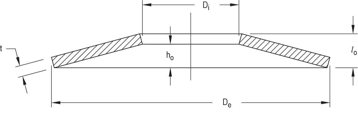
In addition to the classification by groups (which depends on absolute thickness), the standard distinguishes three series according to the h₀/t ratio — the conical free height (h₀) divided by the thickness (t) —, which governs the shape of the spring's force-deflection curve.
For each standardized external diameter there are versions of different series covering different levels of force and travel. For this reason it is common to refer to these springs by the series letter followed by the diameter (e.g. A-50, B-71, C-100).
The standard also allows the manufacture of springs with intermediate thicknesses that, while meeting all other requirements, do not strictly correspond to any of the three series.
h₀ = cone height = l₀ − t (overall free height minus the thickness). Therefore h₀/t = (l₀ − t) / t.
Example — spring 50 × 25.4 × 2.5 × 3.9 mm (De × Di × t × l₀): h₀ = 3.9 − 2.5 = 1.4 mm; h₀/t = 1.4 / 2.5 = 0.56 → Series B.
Exact ranges: Series A h₀/t ≤ 0.4 · Series B 0.4 < h₀/t ≤ 0.75 · Series C 0.75 < h₀/t ≤ 1.3. The De/t ratio (≈ 18 · 28 · 40 for A · B · C) is a typical correlated proportion, not the criterion that defines the series.
Tell us about your use case and our engineering team will advise you on the optimal solution.
The standard specifies the spring steels suitable for manufacturing, listing their standardized DIN designation and their modulus of elasticity. The standard material is chromium-vanadium steel 51CrV4 with a modulus of elasticity of 206,000 N/mm².
For corrosive or high-temperature environments, the standard allows the use of stainless steels (1.4310, 1.4568, 1.4571) and nickel alloys (Inconel 718, Nimonic 90), with the caveat that their modulus of elasticity differs and the load-deflection curve must be recalculated.
| Designation | DIN standard / no. | Type | Typical application | Modulus E |
|---|---|---|---|---|
| 51CrV4 | DIN 17222 · 1.8159 | Chromium-vanadium steel | Standard — all groups | 206,000 N/mm² |
| 51CrMoV4 | DIN 17221 | CrMo-vanadium | Standard — all groups | 206,000 N/mm² |
| CK67 | DIN 1.1231 | Carbon steel | Group 1 only | 206,000 N/mm² |
| CK75 | DIN 1.1248 | Carbon steel | Group 1 only | 206,000 N/mm² |
| X10CrNi18-8 | 1.4310 | Austenitic stainless | Corrosive environments | — recalculate |
| X7CrNiAl17-7 | 1.4568 | Martensitic stainless | Corrosion + load | — recalculate |
| X6CrNiMoTi17-12-2 | 1.4571 | Mo-Ti stainless | Severe corrosion | — recalculate |
| Inconel 718 | 2.4668 | Nickel alloy | High temperature | — recalculate |
| Nimonic 90 | — | Ni-Cr-Co alloy | Severe high temperature | — recalculate |
The standard assigns to each group the manufacturing process that must be used and the minimum surface finishes (Ra roughness) for the different zones of the part.
| Group | Manufacturing | Ra top / bottom faces | Ra inner / outer sides |
|---|---|---|---|
| 1 | Stamping + rounded edges | < 3.2 µm | < 12.5 µm |
| 2 | Stamping + De/Di machining + rounded edges | < 6.3 µm | < 6.3 µm |
| 2* | Fine-blanked + rounded edges (alternative) | < 6.3 µm | < 3.2 µm |
| 3 | Hot/cold forging + full machining + rounded edges | < 12.5 µm | < 12.5 µm |
Surface finishes are not required on parts subjected to shot peening, a process recognized as improving fatigue strength.
After forming, every part undergoes hardening and tempering until it reaches the specified HRC hardness, and a pre-setting process (controlled flattening) to stabilize the geometry and reject parts that do not properly recover their free height.
The standard defines tolerances differentiated by group and, within each group, by thickness range. The tolerances govern both the geometric dimensions and the force at 75 % of travel and the material hardness.
| Group | Thickness (mm) | Thickness tol. (mm) | Height l₀ tol. (mm) | Force tol. at 75 % h₀ | Hardness (HRC) |
|---|---|---|---|---|---|
| 1 | 0.2 — 0.6 | +0.02 / −0.06 | +0.10 / −0.05 | +25 % / −7.5 % | 42 — 52 |
| 1 | > 0.6 — < 1.25 | +0.03 / −0.09 | +0.10 / −0.05 | +25 % / −7.5 % | 42 — 52 |
| 2 | 1.25 — 2.0 | +0.04 / −0.12 | +0.15 / −0.08 | +15 % / −7.5 % | 42 — 52 |
| 2 | > 2.0 — 3.0 | +0.04 / −0.12 | +0.20 / −0.10 | +15 % / −7.5 % | 42 — 52 |
| 2 | > 3.0 — 3.8 | +0.04 / −0.12 | +0.30 / −0.15 | +10 % / −5 % | 42 — 52 |
| 2 | > 3.8 — 6.0 | +0.05 / −0.15 | +0.30 / −0.15 | +10 % / −5 % | 42 — 52 |
| 3 | > 6.0 — 14 | ± 0.10 | ± 0.30 | ± 5 % | 42 — 52 |
| Range (mm) | De — tol. | Di — tol. |
|---|---|---|
| 3 — 6 | 0 / −0.12 | 0 / +0.12 |
| > 6 — 10 | 0 / −0.15 | 0 / +0.15 |
| > 10 — 18 | 0 / −0.18 | 0 / +0.18 |
| > 18 — 30 | 0 / −0.21 | 0 / +0.21 |
| > 30 — 50 | 0 / −0.25 | 0 / +0.25 |
| > 50 — 80 | 0 / −0.30 | 0 / +0.30 |
| > 80 — 120 | 0 / −0.35 | 0 / +0.35 |
| > 120 — 180 | 0 / −0.40 | 0 / +0.40 |
| > 180 — 250 | 0 / −0.46 | 0 / +0.46 |
| > 250 — 315 | 0 / −0.52 | 0 / +0.52 |
| > 315 — 400 | 0 / −0.57 | 0 / +0.57 |
| > 400 — 500 | 0 / −0.63 | 0 / +0.63 |
| > 500 — 600 | 0 / −0.68 | 0 / +0.68 |
F(0.75 h₀) · nominal catalog force. By convention, the standard sets the force tolerances at the point corresponding to 75 % of the maximum deflection.
The standard regulates the allowable clearance between the part and the guiding element (inner pin or outer sleeve). The guiding surfaces must be polished and hardened to a minimum of 55 HRC over at least 0.80 mm of depth.
The most common guidance is provided through the inside diameter by a pin. Guidance can also be provided externally by a sleeve. In long stacks it may be necessary to add spacer discs to prevent buckling. Proper lubrication is essential.
| Guide Ø (mm) | Max. clearance (mm) |
|---|---|
| Up to 16 | 0.2 |
| > 16 — 20 | 0.3 |
| > 20 — 26 | 0.4 |
| > 26 — 31.5 | 0.5 |
| > 31.5 — 50 | 0.6 |
| > 50 — 80 | 0.8 |
| > 80 — 140 | 1.0 |
| > 140 — 250 | 1.6 |
Progressive loss of force under constant load at a defined temperature. The standard sets maximum allowable relaxation values at 20 °C, 80 °C, and 100 °C after a standardized exposure time.
As a practical reference, a stabilized stack loses about 5 % of its force in the first two weeks of service. From then on it should stabilize, with subsequent loss being negligible.
The minimum number of cycles the spring must withstand for a given stress range without developing detectable cracks. The standard includes the corresponding Goodman diagrams for the different groups and materials.
Both behaviors justify the mandatory pre-setting process and, for parts under high dynamic load, shot peening as a mechanical surface-strengthening treatment.
Disc springs manufactured to DIN 2093 / DIN EN 16983 are used in applications that require high axial force in a small space, with a predictable and repeatable response curve.
Bearing preload, clutches, safety valves, hydraulic actuators.
Flange seals, high-pressure valve sealing, critical connections under variable pressure.
Steam and gas turbines, thermal expansion compensators in steam piping.
Tooling clamping, press clutch systems, spindle preload.
Pre-tensioned bearings, vibration dampers, active anchors.
Constant-pressure flanges in piping subjected to thermal cycling.
They are the same standard. DIN 2093 is the historic German designation published by DIN (Deutsches Institut für Normung); DIN EN 16983 is the harmonized European designation, with technically equivalent content. It is common to find both designations on drawings, orders, and catalogs. Any disc spring compliant with DIN 2093 also meets DIN EN 16983.
DIN 2093 / DIN EN 16983 governs the manufacturing and quality characteristics of the disc spring: dimensions, materials, tolerances, processes. DIN 2092 / DIN EN 16984 is the calculation standard: it defines the methods for calculating force, travel, stresses, and service life under different load and stacking modes. In practice, the engineer uses DIN 2092 to size the solution and DIN 2093 to specify the actual part to buy or manufacture.
DIN 2093 / DIN EN 16983 covers disc springs for technical use: parts with a calculable load-deflection curve, suitable for static and dynamic load, standardized in three series (A/B/C) and designed to be stacked. DIN 6796 covers conical spring washers for bolted joints: a single part per joint, sized to 70–90 % of the clamping force of a class 8.8 or 10.9 bolt, for static load only. Rule of thumb: if the joint is a bolt and there is vibration or thermal cycling, use DIN 6796; if you are designing a system with a disc spring whose force and travel are calculated, use DIN 2093.
In Group 3 springs (t > 6 mm) the axial force generated is very high, and the contact footprint with adjacent parts (pin, sleeve, another washer in a stack) would be a point load on the sharp edge. This would cause wear, surface damage, and scatter in the effective force. The bearing surfaces —small machined reliefs on the inner and outer edges— distribute the load over a defined surface, improve repeatability, and allow face-to-face contact between stacked washers. The standard offsets the geometric effect of these surfaces by introducing a reduced thickness t' in the calculations.
Yes. The standard explicitly allows the manufacture of springs with intermediate thicknesses that do not strictly match the A/B/C series, provided all other requirements are met (tolerances, hardness, finishes, relaxation and fatigue testing). Materials outside the standard list (Inconel, Nimonic, other special steels) are also allowed when the application calls for it, with the caveat that the load-deflection (F/s) curve must be recalculated for the modulus of elasticity of the chosen material. Surisa manufactures this kind of custom disc spring to customer drawings.
Tell us about your use case and our engineering team will advise you on the optimal solution.