What are cartridge heaters and what types are there?
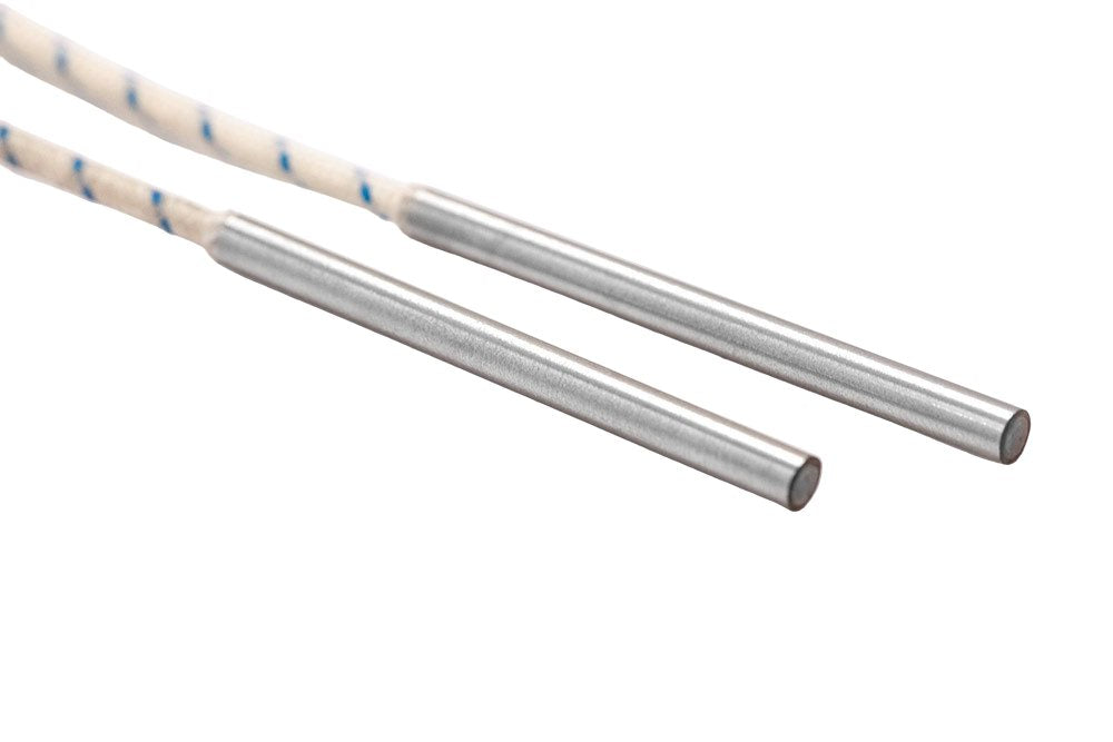
High-density cartridge heaters —also known as cartridge heating elements, high-power tubular cartridges or, in their international technical terminology, high-performance cartridge heaters— are industrial electric heating elements built to deliver large amounts of thermal power in a very small volume. What sets them apart from conventional cartridge heaters is their high watt density, which reaches values of up to 50 W/cm² (320 W/in²) at the sheath surface.
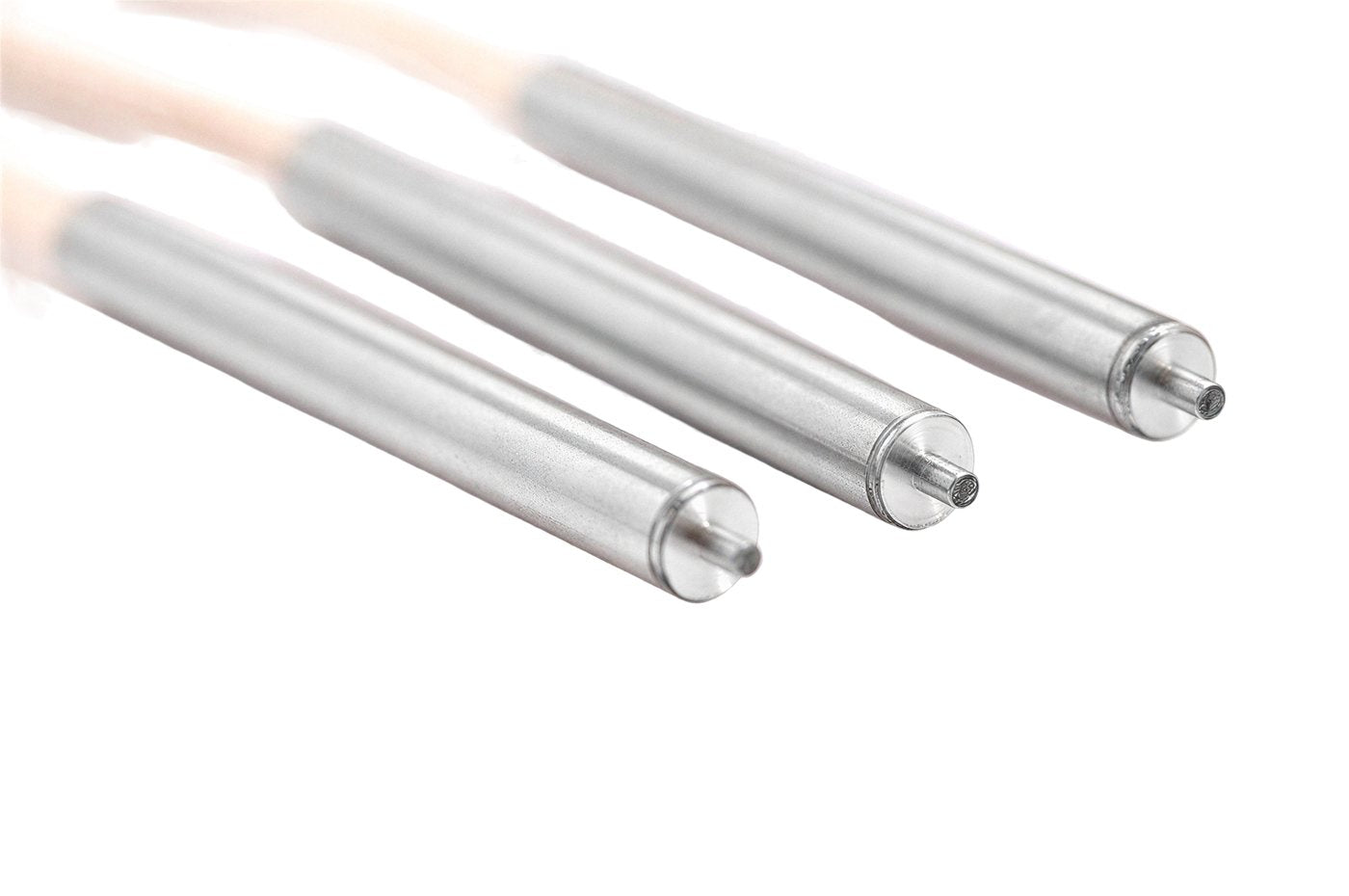
Their construction is based on a chromium-nickel stainless steel tube with a NiCr 8020 resistance wire wound on a ceramic core and insulated with highly compacted magnesium oxide (MgO). This compaction is what enables the high heat transfer between the wire and the sheath, and it is what distinguishes a high-density cartridge heater from traditional low-density (non-compacted) cartridge heaters.
Configuration comparison table
Comparison of Surisa's cartridge heater configurations (standard, integrated thermocouple, PT100, bipolar Ø 4, low voltage and sensing tip) by application, construction, dimensions, electrical characteristics, sensor and safety.
Attribute
Standard
Integ. thermocouple
PT100 sensor
Ø 4.0/4.5 bipolar
Low voltage
Sensing tip
Low-density
Main application
Molds, blocks and nozzles; general use
Temperature control without an external probe
Accuracy and traceability (medical, pharma, food)
Very small parts or narrow bores
Enhanced electrical safety / low voltage
Ambient temperature control (sealing)
Less demanding applications in watt density
Sheath
CrNi steel · base welded in protective atmosphere
CrNi steel · base welded in protective atmosphere
CrNi steel · base welded in protective atmosphere
CrNi steel · laser-welded base
CrNi steel · laser-welded base
CrNi steel · base welded in protective atmosphere
Stainless steel or brass · crimped base · opt. leak-tight weld
Insulation
Pure highly compacted MgO
Pure highly compacted MgO
Pure highly compacted MgO
Pure compacted MgO
Pure compacted MgO
Pure highly compacted MgO
Pure compacted MgO
Resistance wire
NiCr 8020
NiCr 8020
NiCr 8020
NiCr 8020
NiCr 8020
NiCr 8020
NiCr 8020
Leads
300 mm (12") nickel wire over fiberglass · ceramic seal
500 mm (20") heating + 500 mm (20") thermocouple · 480 mm (19") sleeve
500 mm (20") heating + 500 mm (20") PT100 (PTFE) · 480 mm (19") sleeve
Nickel-PTFE · exit through head
250 mm (10") direct · opt. dual-side
300 mm (12") heating + 300 mm (12") thermocouple · 280 mm (11") sleeve
Nickel-fiberglass +350 °C (660 °F) · nickel-PTFE +260 °C (500 °F) · silicone +180 °C (355 °F)
Diameters
6.5–20 mm · 1/4"–5/8"
6.5–20 mm · 1/4"–5/8"
6.5–20 mm · 1/4"–5/8"
4.0 · 4.5 mm · 5/32"–3/16"
4.5 mm · 3/16" (4.0 special)
6.5 mm · 1/4"
To order
Dimensional tolerance
−0.01 to −0.05 mm · −0.0004 to −0.0020" (by Ø)
−0.01 to −0.05 mm · −0.0004 to −0.0020" (by Ø)
−0.01 to −0.05 mm · −0.0004 to −0.0020" (by Ø)
−0.01 to −0.03 mm · −0.0004 to −0.0012"
−0.01 to −0.03 mm · −0.0004 to −0.0012"
−0.01 to −0.03 mm · −0.0004 to −0.0012"
± 0.10 mm (± 0.004")
Lengths
40–300 mm · 1½"–12"
40–300 mm · 1½"–12"
35–300 mm · 1 3/8"–12"
20–100 mm · 3/4"–4"
40–100 mm · 1½"–4"
40–60 mm · 1½"–3"
50–4,000 mm · 2"–157"
Length tolerance
≤100 → ±2 · 100–300 → ±5 mm (±0.08"–0.20")
≤100 → ±2 · 100–300 → ±5 mm (±0.08"–0.20")
≤100 → ±2 · 100–300 → ±5 mm (±0.08"–0.20")
≤100 → ±2 mm (±0.08")
≤100 → ±2 mm (±0.08")
≤100 → ±2 mm (±0.08")
± 1.5 % · min. ± 2 mm (± 0.08")
Voltage
230 V
230 V
≤230 V
≤230 V
24 V · max. 48 V
230 V
230 V / 400 V
Power
100–4,000 W
100–4,000 W
≤2,000 W
≤200 W
63–160 W
115–300 W
To order
Power tolerance
±10 %
±10 %
±10 %
±10 %
±10 %
±10 %
+5 % / −10 %
Max. watt density
50 W/cm² (320 W/in²)
50 W/cm² (320 W/in²)
50 W/cm² (320 W/in²)
20 W/cm² (130 W/in²)
—
50 W/cm² (320 W/in²)
5 W/cm² (32 W/in²)
Max. sheath temp.
750 °C (1,380 °F)
750 °C (1,380 °F)
750 °C (1,380 °F)
260 °C (500 °F)
—
750 °C (1,380 °F)
500 °C (930 °F) stainless · 300 °C (570 °F) brass
Max. current
—
—
—
4.0 A
—
—
—
Temperature sensor
—
Thermocouple L / J / K · base · floating
PT100 DIN EN 60751 cl. B · base
Optional thermocouple · head
Optional thermocouple
Thermocouple in tip · senses the surroundings
—
High voltage (HV)
1,500 V-AC
1,500 V-AC
—
<48 V → 500 / ≥48 V → 1,000 V-AC
—
—
1,500 V-AC
Insulation resistance
≥5 MΩ at 500 V-DC
≥5 MΩ at 500 V-DC
—
≥5 MΩ at 500 V-DC
—
—
≥2 MΩ at 500 V-DC
— not specified or not applicable · Reference data per manufacturer datasheets. Special versions are confirmed subject to technical review.
02
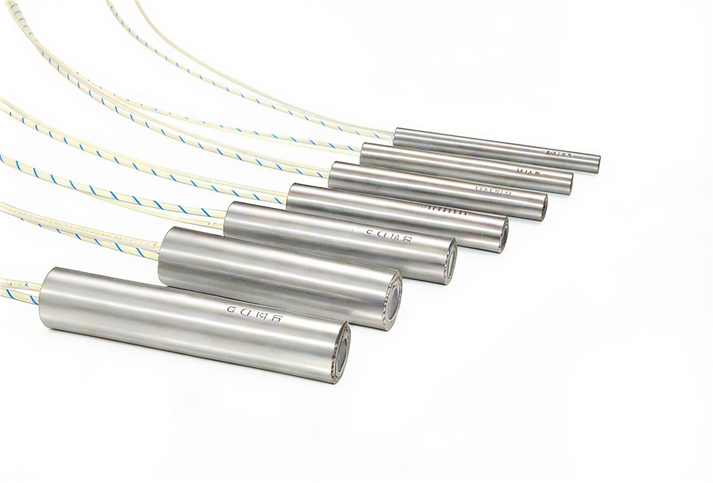
Standard high-density cartridge heaters
The base and most widely used configuration, designed for the most demanding operating conditions. They are the evolution of conventional low-density cartridge heaters with a brass or steel sheath: a recommended watt density of up to 50 W/cm² (320 W/in²) and operating temperatures of up to 750 °C (1,380 °F) ensure optimal performance and quality across a wide range of thermal processes.
Dimensional tolerance
Diameter and length tolerances of the standard high-density cartridge heater.
Dimension
Tolerance
Ø 6.5 · 8 mm · 1/4"–5/16"
−0.01 to −0.03 mm (−0.0004 to −0.0012")
Ø 10–16 mm · 3/8"–5/8"
−0.02 to −0.04 mm (−0.0008 to −0.0016")
Ø 20 mm · 3/4"
−0.03 to −0.05 mm (−0.0012 to −0.0020")
Length ≤ 100 mm · ≤ 4"
± 2 mm (± 0.08")
Length > 100–300 mm · 4"–12"
± 5 mm (± 0.20")
Standard cartridge heaters
03
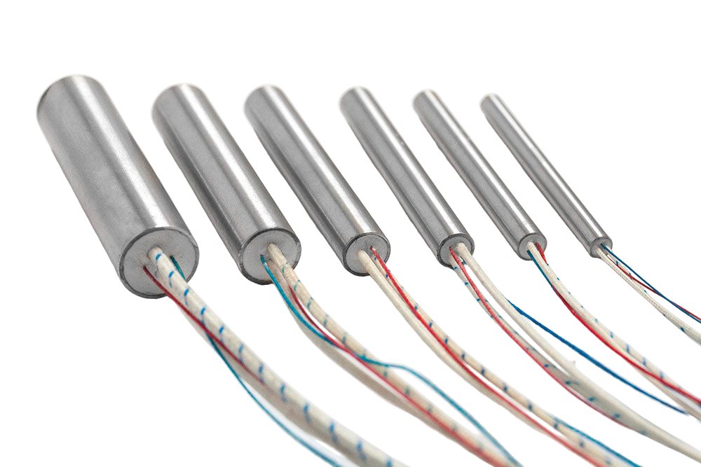
Cartridge heaters with integrated thermocouple
Recommended when there is no room in the part to fit a separate probe. The thermocouple is integrated into the cartridge heater itself and closes the control loop directly. Depending on the application, the measuring point can be located at the base, in the middle zone or at any other point; the electrical configuration can be floating (potentialfrei) or grounded. The most common types are L / J (Fe-CuNi) and K (NiCr-Ni); other types on request. Standard items are kept in stock and delivered within 24–48 h.
Dimensional tolerance
Diameter and length tolerances of the cartridge heater with integrated thermocouple.
Dimension
Tolerance
Ø 6.5 · 8 mm · 1/4"–5/16"
−0.01 to −0.03 mm (−0.0004 to −0.0012")
Ø 10–16 mm · 3/8"–5/8"
−0.02 to −0.04 mm (−0.0008 to −0.0016")
Ø 20 mm · 3/4"
−0.03 to −0.05 mm (−0.0012 to −0.0020")
Length ≤ 100 mm · ≤ 4"
± 2 mm (± 0.08")
Length > 100–300 mm · 4"–12"
± 5 mm (± 0.20")
Cartridge heaters with thermocouple
Let's talk about your project
Tell us about your use case and our engineering team will help you choose the optimal solution.
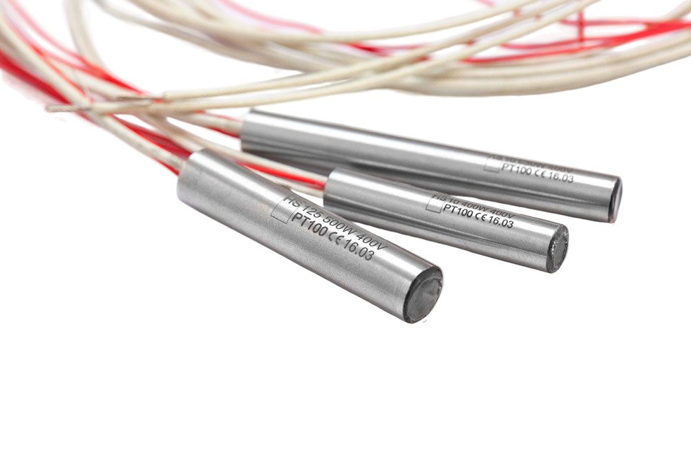
For processes where accuracy and traceability are critical (medical, pharmaceutical, food). Custom build only. The sensor is always placed in the base zone; for technical reasons, the area around the measuring point is unheated, and to compensate for the resulting temperature gradient in the sheath, the cartridge heater is reinforced with extra power (boost) in the zone immediately around the measuring point.
Dimensional tolerance
Diameter and length tolerances of the cartridge heater with PT100 sensor.
Dimension
Tolerance
Ø 6.5 · 8 mm · 1/4"–5/16"
−0.01 to −0.03 mm (−0.0004 to −0.0012")
Ø 10–16 mm · 3/8"–5/8"
−0.02 to −0.04 mm (−0.0008 to −0.0016")
Ø 20 mm · 3/4"
−0.03 to −0.05 mm (−0.0012 to −0.0020")
Length 35–300 mm · 1 3/8"–12"
≤100 → ±2 · 100–300 → ±5 mm (±0.08"–0.20")
Cartridge heaters with PT100
05
Ø 4.0 / 4.5 mm · 5/32"–3/16" cartridge heaters (bipolar)
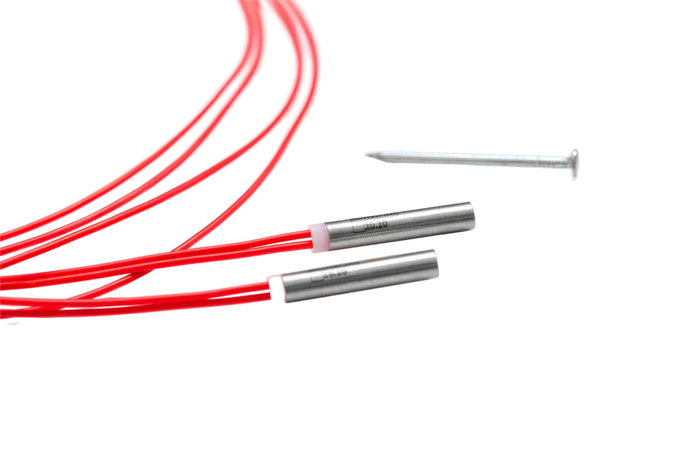
A high-density compacted cartridge heater with flexible PTFE-insulated nickel leads that exit directly from the cartridge body. Especially suited for heating very small parts and extremely narrow bores where standard diameters do not fit. Special build only. It can optionally include a thermocouple with the measuring point at the head.
Dimensional tolerance
Diameter and length tolerances of the Ø 4.0 / 4.5 mm bipolar cartridge heater.
Dimension
Tolerance
Ø 4.0 / 4.5 mm · 5/32"–3/16"
−0.01 to −0.03 mm (−0.0004 to −0.0012")
Length 20–100 mm · 3/4"–4"
± 2 mm (± 0.08")
Bipolar cartridge heaters Ø 4.0/4.5
06
Low-voltage cartridge heaters (24–48 V)
For SELV operation or 24 V systems. The current return runs through the cartridge sheath itself, which limits the maximum voltage to 42 V (within Europe, protective voltages of up to 48 V are partly allowed). Power varies within the technical possibilities. Standard items are kept in stock; they can also be custom built. Optionally with an integrated thermocouple.
Dimensional tolerance
Diameter and length tolerances of the low-voltage cartridge heater.
Dimension
Tolerance
Ø 4.5 mm · 3/16" (4.0 special)
−0.01 to −0.03 mm (−0.0004 to −0.0012")
Length 40–100 mm · 1½"–4"
± 2 mm (± 0.08")
Low-voltage cartridge heaters
07
Cartridge heaters with sensing tip
The thermocouple sits in a reduced extension (the "tip") of the cartridge heater, so it is no longer next to the heating coil —as is the case with standard cartridge heaters with an integrated thermocouple. The decisive advantage is that these cartridge heaters do not measure their own temperature but that of the surroundings or the heated part, which allows more precise and uniform process temperature control. A common solution in heat sealing. Standard items in stock; custom builds also available.
Dimensional tolerance
Diameter and length tolerances of the cartridge heater with sensing tip.
Dimension
Tolerance
Ø 6.5 mm · 1/4"
−0.01 to −0.03 mm (−0.0004 to −0.0012")
Length 40–60 mm · 1½"–2 3/8"
± 2 mm (± 0.08")
Cartridge heaters with sensing tip
08
Low-density cartridge heaters
An economical alternative to the high-density cartridge heater (hochverdichtet) for simple use cases, with a maximum watt density of 5 W/cm² (32 W/in²) and an operating temperature of up to 500 °C (930 °F). It is suitable for undemanding applications but is not recommended when the tool is subject to heavy mechanical stress (for example, vibration). Custom builds available: other dimensions, voltages, mounting features, unheated zones and power distributions on request. Sheath in stainless steel (up to 500 °C / 930 °F) or brass (up to 300 °C / 570 °F).
Dimensional tolerance
Diameter and length tolerances of the low-density cartridge heater.
Dimension
Tolerance
Diameter (depending on grinding)
± 0.10 mm (± 0.004")
Length 50–4,000 mm · 2"–157"
± 1.5 % · min. ± 2 mm (± 0.08")
Low-density cartridge heaters
09
Special versions and custom builds
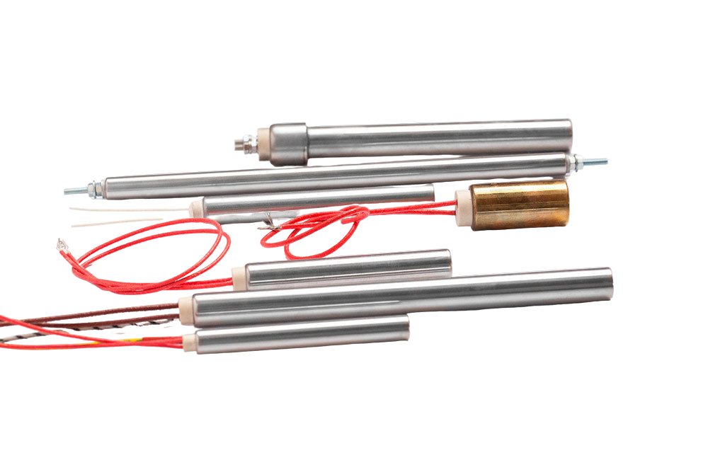
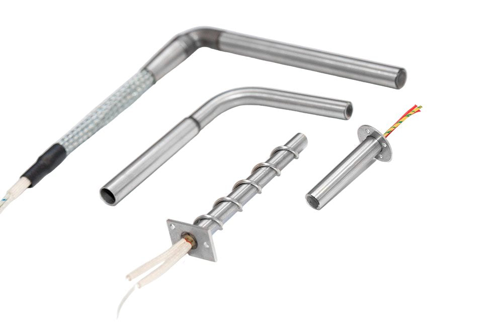
As a manufacturer of high-density cartridge heaters, we meet each customer's individual needs and produce custom cartridge heaters in diameters from 4.0 to 20 mm (5/32"–3/4"). All requirements are considered and implemented in development and production within our technical possibilities: different voltages, tailored power boost at the ends, separately switchable heating zones and an integrated PT100 or thermocouple.
Custom build ranges
Ranges available on request for custom cartridge heaters: diameter, length, voltage, watt density, temperature and tolerance.
Parameter
Range on request
Diameter
4.0 to 20 mm · 5/32"–3/4"
Length
20 to 3,000 mm · 3/4"–118"
Voltage
6 V to 500 V
Max. watt density
50 W/cm² (320 W/in²)
Max. sheath temp.
750 °C (1,380 °F)
Power tolerance
± 10 % · ± 5 % by agreement
Custom versions
— Customization options
— Power boost
Especially in plastics and packaging, uniform heat delivery is required along the entire element mounted in the tool (sealing jaws, platens, heated bars). By boosting the end zones, the heat delivery is individually adjusted to the desired effect.
— Multi-zone heating
Design with a three- and four-wire system (heating zones): by switching the phases across the windings arranged in parallel, the total power is regulated as needed. Available from Ø 12.5 mm (1/2").
— Integrated sensors
PT100 or thermocouple (types L / J Fe-CuNi and K NiCr-Ni), in a floating (potentialfrei) or grounded version, with the measuring point in the position the process requires.
— Connections and protection
Multiple connection options, angled heads and side exits, various power leads, metal protective tubes, fiberglass sleeves, stainless steel braid, and more.
10
Installation and assembly
Thermal performance and service life depend directly on the mechanical fit between the cartridge heater and its bore. Excessive clearance prevents heat conduction, overheats the internal winding and drastically shortens the component's life. Recommended bore tolerance: ISO H7.
Clean and deburr the bore before inserting the cartridge heater.
Apply heat-conductive assembly paste above 400 °C (750 °F).
Do not subject the cartridge heater to impacts during insertion.
Protect the wiring from direct contact with surfaces > 200 °C (390 °F).
Locate the sensor zone at the most critical point of the process.
Bore tolerance · ISO H7
Bore tolerance per ISO H7 as a function of the cartridge heater's nominal diameter.
Cartridge nominal Ø
Bore tolerance (H7)
> 3 to 6 mm (0.12"–0.24")
+0.012 / −0 mm (+0.0005")
> 6 to 10 mm (0.24"–0.39")
+0.015 / −0 mm (+0.0006")
> 10 to 18 mm (0.39"–0.71")
+0.018 / −0 mm (+0.0007")
> 18 to 30 mm (0.71"–1.18")
+0.021 / −0 mm (+0.0008")
11
Industrial applications
Any process that requires generating concentrated thermal power in a small bore.
Small ovens, primary packaging sealing, blister machines.
06
VFFS / HFFS packaging machinery
Longitudinal and cross sealing jaws.
07
Footwear and engineering plastics
Vulcanizing presses, thermoforming molds.
08
Laboratory and prototyping
Small ovens, thermal baths, test equipment.
12
Frequently asked questions
01What watt density can a high-density cartridge heater reach?
Up to 50 W/cm² (320 W/in²) at the sheath surface, with temperatures of up to 750 °C (1,380 °F) —5 to 10 times more than a conventional low-density cartridge heater. The low-voltage and Ø 4 mm (5/32") versions work at lower densities, typically 20 W/cm² (130 W/in²).
02What's the difference between an integrated thermocouple and a sensing tip?
The integrated thermocouple measures the temperature of the cartridge heater itself (protecting against overheating). The sensing tip, physically separated from the heated zone, measures the temperature of the surroundings or the heated part —the most precise option for controlling process temperature (e.g. sealing jaws).
03When should you use a PT100 instead of a thermocouple?
The PT100 offers higher accuracy and better repeatability, ideal for pharmaceutical, food and medical applications with critical traceability. Its range is lower (up to ~600 °C / 1,110 °F). Above that temperature, or where exact accuracy is not required, the thermocouple is more practical and economical.
04What tolerance should the bore have?
ISO H7 is recommended. For Ø 10 mm (3/8"), the bore is machined to Ø 10 +0.018 / −0 mm (+0.0007"). Larger clearance reduces heat transfer and accelerates wear; above 400 °C (750 °F) it is advisable to use thermal assembly paste.
05Can a non-uniform power distribution be manufactured?
Yes. Power boost concentrates power at the ends or specific zones. Multi-zone heating with independent windings is also possible, available from Ø 12.5 mm (1/2").
06What is the typical lead time?
Standard configurations Ø 6.5–20 mm · 1/4"–3/4" (standard or with thermocouple) are kept in stock in Barcelona and delivered within 24–48 h. Special versions require dedicated manufacturing with a lead time depending on the project.
Let's talk about your project
Tell us about your use case and our engineering team will help you choose the optimal solution.