


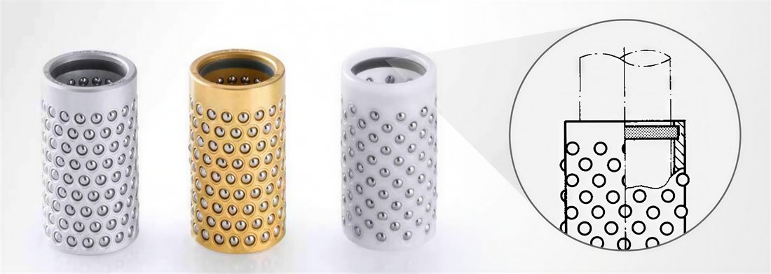
With installation assistance
The upper head incorporates a geometry that eases positioning of the cage onto the guide pillar. Essential when the die set carries several guide units at once.
 Official distribution in Spain
The guide elements that, together with the guide pillar, align the two halves of a stamping die. Complete Steinel Normalien range with seven guide types and load capacities certified to DIN ISO 14728-1.
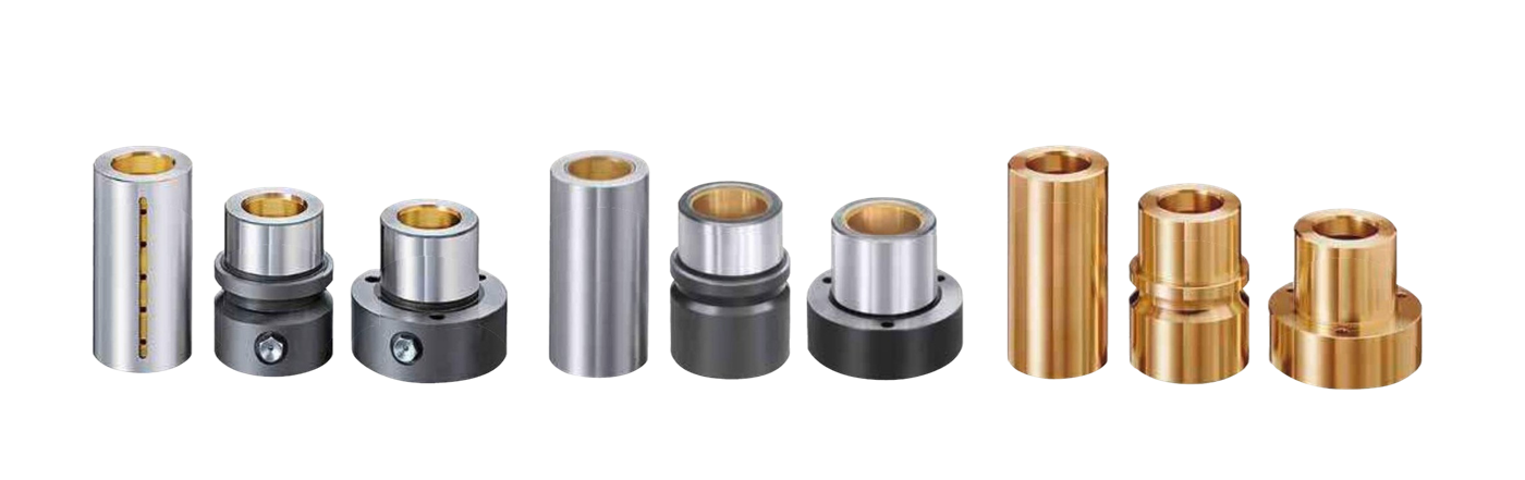
The guide elements —the guide bushes and ball cages (in international technical terminology, guide bushes and ball cages for die sets)— are the components that work paired with the guide pillar to ensure alignment between the upper and lower die shoe on every press stroke. This alignment, held to instrumentation-grade tolerances, determines the cutting clearance between punch and die and, by extension, the edge quality of the stamped part and the tool's service life.
Surisa is the Spanish distributor for the complete range from Steinel Normalien GmbH, the leading German manufacturer of standardized die-set components. The products comply with DIN 9831 / ISO 9448 for plain guide elements and DIN ISO 14728-1 for the dynamic load capacity of the cages.
The three available guide technologies cover complementary working ranges. The choice is not a matter of quality but of suitability for the application.
| Technology | Stroke | Side thrust | Speed | Maintenance |
|---|---|---|---|---|
| Plain | Full pillar stroke | High — distributed over the surface | Up to 20 m/min | Periodic lubrication or solid lubricant |
| Ball cages | Limited by the cage (Stroke/2 rule) | Medium | 30–40 m/min and above | Almost none |
| Roller cages | Limited by the cage (Stroke/2 rule) | Very high — 6–12× a ball of the same Ø | ≥ 40 m/min | Almost none |
Stroke/2 rule. In rolling guides, during the stroke the cage advances half the axial travel of the guide element. This limits the usable stroke to the distance available between the cage and the assembly's mechanical stops.
The main advantage of the Steinel Normalien system is that all guide elements share the same external diameter per housing family. A die set designed for a plain guide can be converted into a die set with ball guiding without additional machining operations — you simply replace the guide element.
Our engineers help you choose between a plain guide, ball cage, or roller cage based on side thrust, stroke, and working speed.
The three plain technologies share the mounting geometry but differ in the lubrication system and materials. Click each type to expand its data.
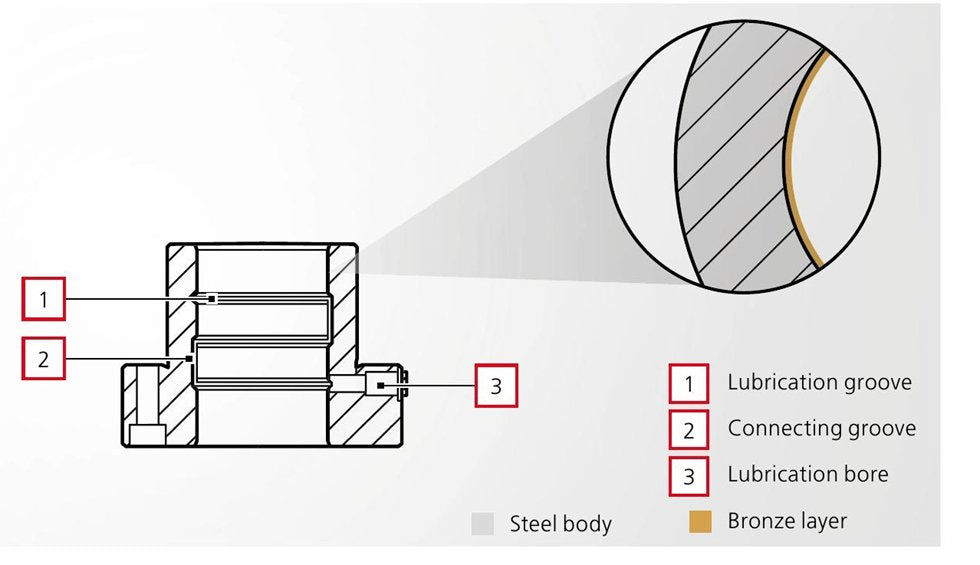
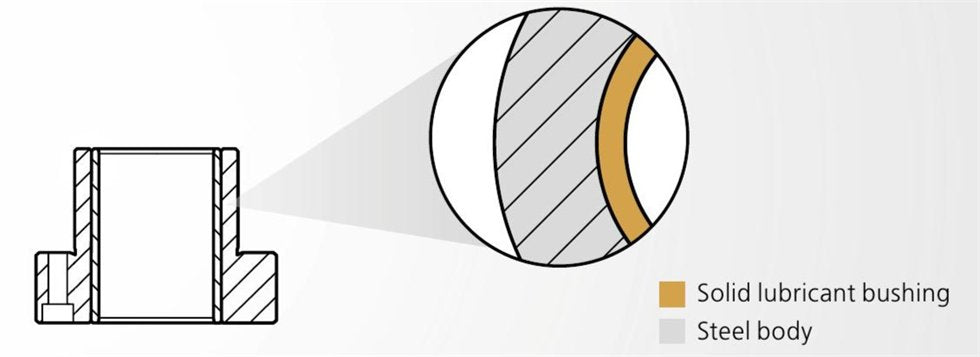
 Steel with bronze coatingSteel / bronze

 With solid lubricantSolid lubricant

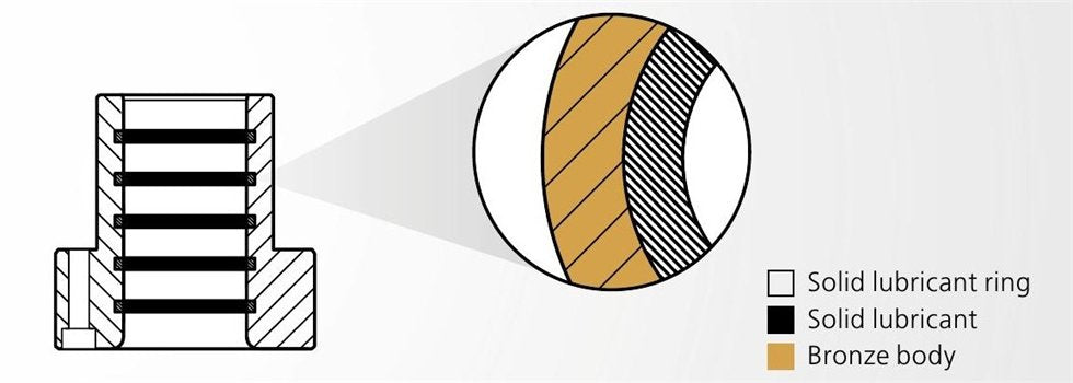
 Bronze with solid lubricant ringsGraphite rings

Ball cages (ball cage retainers) replace sliding contact with rolling contact. The precision hardened steel balls are arranged in an axial spiral, so that each ball travels its own raceway — this increases service life by avoiding repeated indentation.
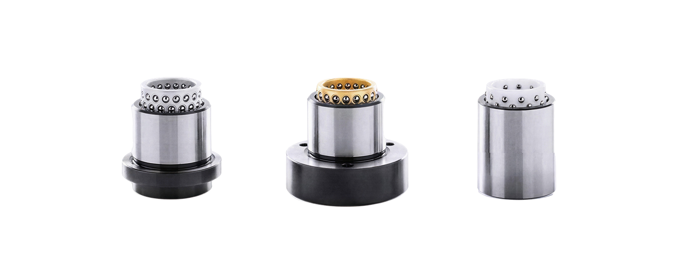
The upper head incorporates a geometry that eases positioning of the cage onto the guide pillar. Essential when the die set carries several guide units at once.
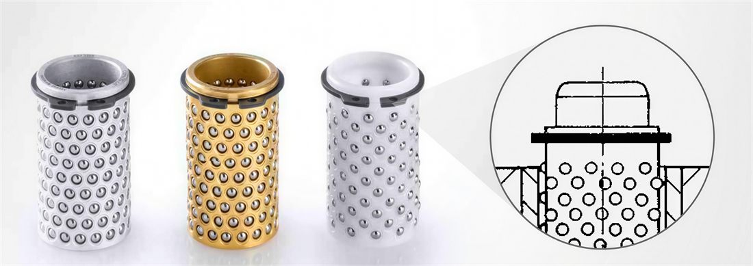
The ring prevents the cage from coming out of its housing during tool disassembly. In operation, it also prevents progressive cage wandering over long strokes.
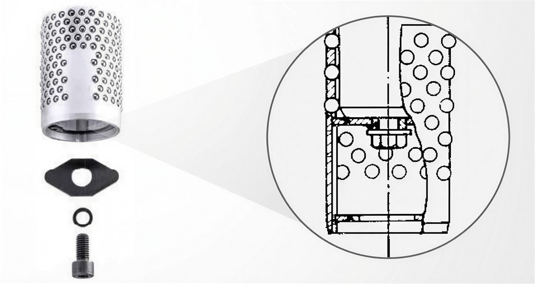
Aluminum only. During full retraction of the guide element, the locking plate retains the cage on the guide pillar. The solution for applications where the pillar and the guide element separate completely on every cycle.
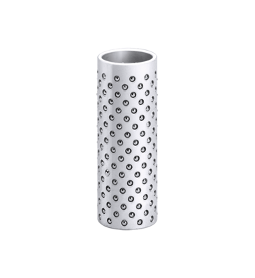
Typical application: dies with frequent disassembly, tools with several guide units.
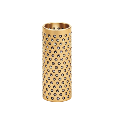
Typical application: optical and electronic measuring devices, high-volume production.
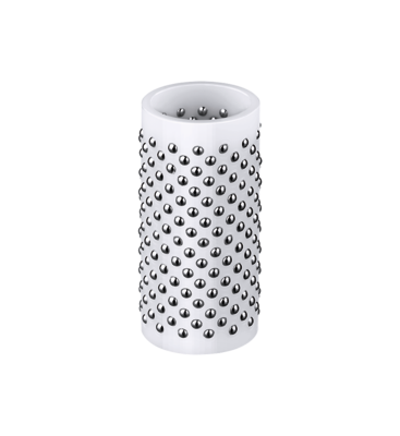
Typical application: high cadence, environments with chemical corrosion.
In roller guides the balls are replaced by barrel-shaped cylindrical rollers (saddle shape). The main advantage is load capacity.
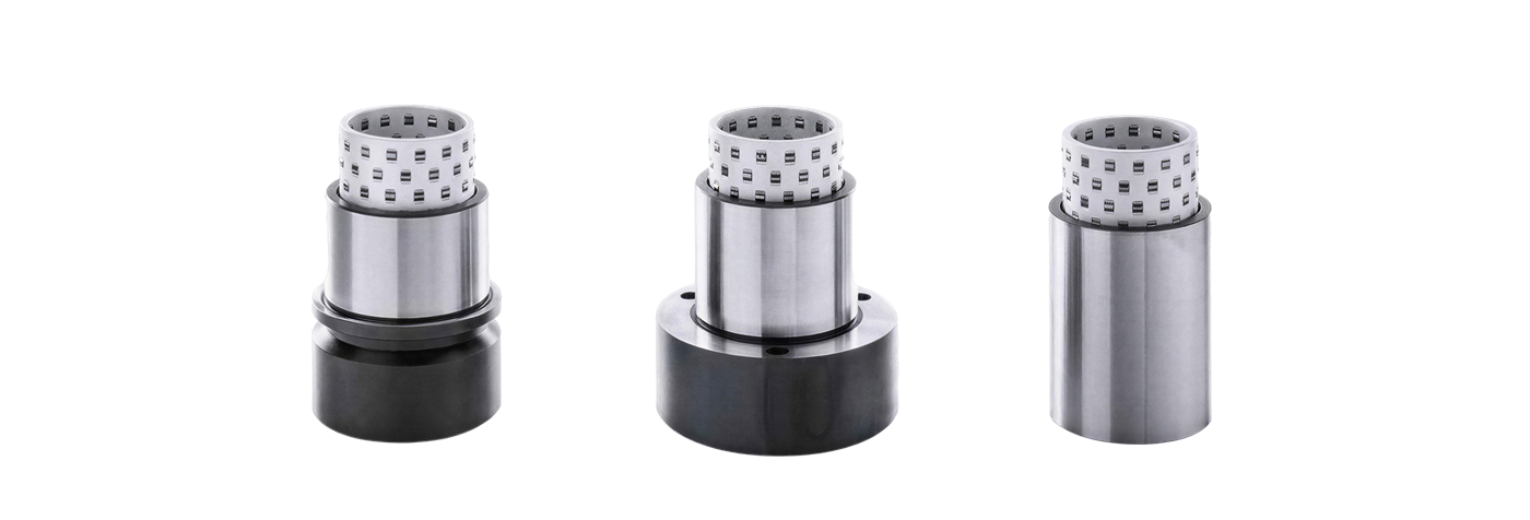


| Configuration | Fixing |
|---|---|
| Smooth | Glued with Loctite 603 adhesive (Steinel ref. SZ9742). Do NOT press — pressing deforms the internal diameter. The adhesive surfaces must be free of grease. |
| Shoulder | The shoulder is pressed against the plate with clamps or screws. |
| Flange | The flange is pressed against the plate with screws. |
Additional critical rules
Steinel Normalien guide elements are used in any application that combines stamping press, blanking or forming with high-precision alignment requirements.
Progressive dies for body panels, drawing, and chassis and frame components.
Deep drawing and cutting dies for sheet metal.
High-cadence progressive dies for terminals, contacts, and housings.
Cutting and drawing dies for cans, lids, and packaging components.
Fine blanking — tools with very tight dimensional tolerances.
Standardized die sets with interchangeable guide elements for the machine shop.
Plain (smooth) guide elements must be glued with Loctite 603 adhesive (Steinel reference SZ9742), never pressed in. The reason is geometric: radial pressure deforms the internal diameter of the guide element, which alters the nominal clearance with the pillar or the preload of the ball cage. The bonding surfaces must be completely free of grease. Guide elements with a shoulder or a flange, on the other hand, are mounted by pressing the shoulder or the flange against the plate with auxiliary clamps or screws.
The plain guide (steel/bronze or solid lubricant) accepts the highest lateral load because it distributes it over the entire surface of the guide element, and it allows strokes as long as the pillar itself. It is the choice for dies with significant side thrust. The ball cage offers the highest precision and the best speed/maintenance ratio, but its usable stroke is limited by the Stroke/2 rule and it tolerates lateral loads less well. The roller cage combines high speed with load capacity (a roller withstands 6–12× the static load of a ball of the same Ø), but it only allows longitudinal movements — not rotational ones.
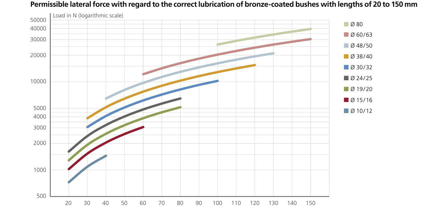
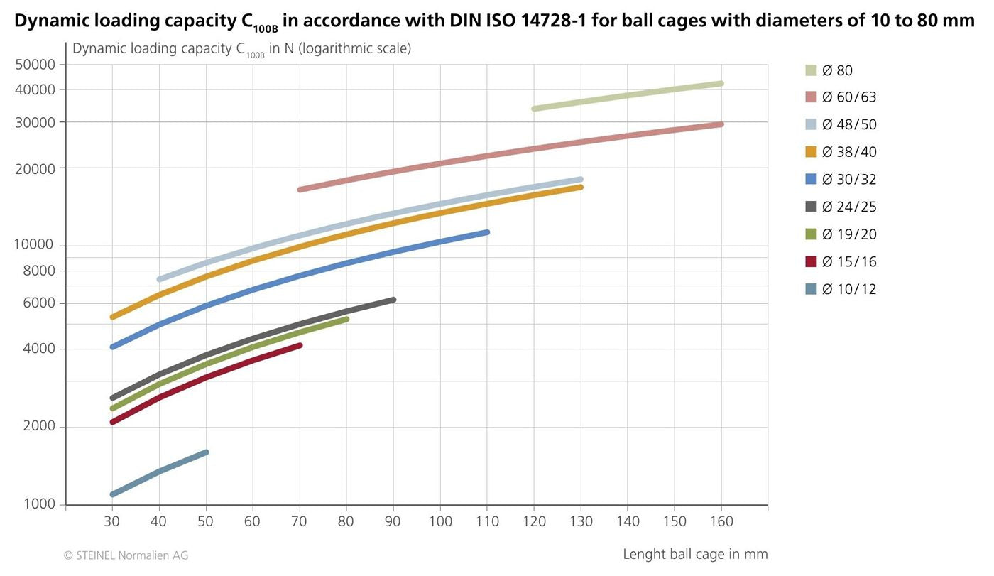
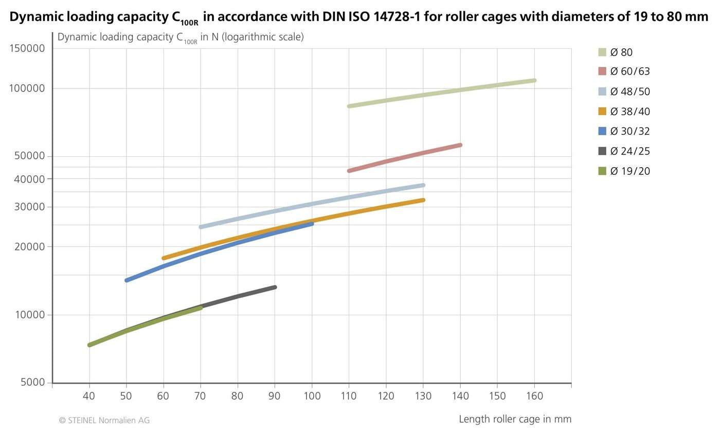
The dynamic load capacity of Steinel cages is certified as C₁₀₀B to DIN ISO 14728-1 (ball cages) and C₁₀₀R to DIN ISO 14728-1 (roller cages). The values cover diameters from 10 to 80 mm and cage lengths up to 160 mm, with detailed curves in the technical catalog for each Ø × length combination. The capacity increases with cage length and with diameter, since both parameters increase the number of balls or rollers in simultaneous contact.
During the movement of the guide element on the pillar with a ball or roller cage, the cage travels half the stroke of the guide element. This means that for a total travel of 60 mm of the guide element, the cage moves 30 mm. As a result, the usable length available for the cage must be at least (stroke / 2) + cage length + retention margins. A short cage will limit the usable stroke of the die; a cage that is too long will increase the assembly height without adding any load capacity.
To ensure the nominal clearances and preloads, it is advisable to work with a pillar and guide element from the same range and series. The h3 tolerances of the pillar are designed to pair with the internal diameters of the corresponding guide element — 2–7 µm clearance in the steel/bronze guide element, 3–10 µm with solid lubricant, controlled preload with a ball cage. Mixing manufacturers can introduce out-of-range deviations and compromise the precision and service life of the system.
We distribute the complete Steinel Normalien range in Spain. We advise you on guide types, interchangeable combinations, and delivery times.