


— Type
Helical spring that works by applying a torque over a rotation.
Helical springs that work by applying a torque to a rotational movement, not an axial load. Their legs transmit and absorb the torque as they rotate.
Despite the name, the wire works in bending. And a critical detail: the spring must always be loaded in the direction that closes the coil.
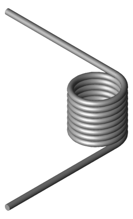
Elastic components designed to work by applying a torque to a rotational movement. Their active part is a helical coil of steel wire whose ends —formed into different leg geometries— transmit and absorb the torque generated by the rotation.
Unlike compression or extension springs, the load does not act axially but angularly: the legs rotate around the body axis. This makes them essential in return, closing or rotary indexing mechanisms, wherever a controlled return torque is needed after a rotation.
The behaviour is linear: the torque grows in proportion to the angle rotated according to its torque rate, M = k · θ. A well-sized spring offers a long service life, typically longer than that of an equivalent extension spring.
Helical spring that works by applying a torque over a rotation.
Angular (torque M), not axial — the legs rotate around the axis.
Bending (despite the name); peak stress at the inner fibre.
Linear: M = k · θ (torque rate per degree of rotation).
Straight tangential leg · radial · bent / hook · custom.
Always the one that closes the coil (reduces the diameter).
Carbon steel · stainless 302/304/316 · high-performance alloys.
Custom to drawing, with the winding direction specified.
Although the name suggests otherwise, the wire of a torsion spring does not work in torsion, but in bending: the torque is transmitted along the coiled wire as a bending stress.
Peak stress concentrates at the inner fibre of each coil (curvature effect, Wahl factor), and that is where fatigue cracks start.
Practical design tip: raising the spring index (C = Dm/d) reduces that inner stress. Going from C = 4 to C = 6 lowers the inner-fibre stress by around 12%, improving fatigue life.
M = k · θ
total torqueC = Dm / d
spring indexWhen the legs deflect in the correct direction, the body reduces its internal diameter and lengthens slightly (about one wire diameter per full turn of the leg). Clearance with the guide shaft must be allowed for.
The basic dimensions of a torsion spring: wire diameter (Ø d), outer (De) and mean (Dm) diameter, coiled body length (Lk) and the legs formed at both ends.
The response is linear and starts at the origin: the torque grows in proportion to the angle rotated according to the torque rate, M = k · θ.
The dimensions on the left define the spring geometry —wire, diameters, body length and legs—. The torque–angle curve on the right describes its response: the torque grows linearly with the angle rotated, M = k · θ.
A torsion spring must always be loaded in the direction that reduces the body diameter (closes it onto the arbor). In that direction the residual manufacturing stresses are favourable; in the opposite direction they are unfavourable and the spring fails sooner.
That is why the winding direction —right-hand or left-hand— must always be specified on the drawing: a right-hand and a left-hand spring are not interchangeable, and omitting this detail is one of the most costly mistakes in sourcing torsion springs.
The working direction of rotation (clockwise or counterclockwise) determines the required winding direction and the position of the legs (left or right) in the assembly. It should be defined together with the working angle and the torque.
Loaded in the direction that closes the coil (reduces Ø, left) the residual stresses are favourable. In the direction that opens it (increases Ø, right) they are unfavourable and the spring fails sooner.
A torsion spring is normally mounted on a shaft or arbor aligned with the rotation axis of the mechanism. As the internal diameter reduces under load, the guiding must be sized carefully.
More compact, but with friction between coils.
Reduces friction and hysteresis when these are critical.
The arbor is sized at ~90% of the spring internal diameter once contracted, leaving clearance. Too large and the spring binds; too small and it allows buckling.
Tell us the nominal torque, working angle, direction of rotation, available space, leg type and environment — and our engineering team will help you size the optimal torsion spring. Manufacturer since 1975.
The legs are formed according to the anchoring and available space of each mechanism. The leg type determines the assembly and how the spring transmits the torque to the surrounding parts.
The most common; direct tangential exit, the first choice in most mechanisms.
For radial anchorings aligned with the rotation axis of the mechanism.
Hooks onto a pin or part; closes the anchoring without added elements.
One right-hand body and one left-hand joined: the total torque is the sum of both.
Legs formed to suit the mechanism when no standard one fits.
Two coiled bodies —one right-hand and one left-hand— joined and working in parallel: the total torque is the sum of the torque of both bodies. It delivers high torque while keeping the individual stresses under control. Each section is designed separately.
The choice of material depends on the working environment: in dry conditions mechanical strength prevails; with moisture or chemical agents, corrosion resistance.
| Environment | Recommended material | Note |
|---|---|---|
| General use · dry | Music wire / carbon steel | Best mechanical strength and cost-performance ratio in dry environments. |
| Humid · corrosion | Stainless steel AISI 302 / 304 | Corrosion resistance for humid environments. |
| Aggressive chemical / salt water | Stainless steel AISI 316 | Maximum corrosion resistance among the common stainless grades. |
| Temperature · hygiene · extreme corrosion | High-performance alloys (on request) | For special corrosion, temperature or hygiene requirements. |
In dry conditions, carbon steel / music wire for its higher strength. With moisture you move to stainless 302/304/316; for extreme corrosion, temperature or hygiene, high-performance alloys on request.
As a reference, a well-sized torsion spring offers a typical service life longer than that of an equivalent extension spring.
Torsion springs appear in any mechanism that requires a controlled return torque after a rotation: return mechanisms, rotary indexing, pedals, household appliances, automotive and clamps. To size the working angle, the nominal torque, the winding direction and the leg geometry, Surisa's technical team, a specialized manufacturer since 1975, offers free engineering support.
They return an element to its rest position after a rotation: hinges, latches, catches and hinged lids that must close on their own.
They hold and return discrete angular positions in ratchets, selectors and rotary indexing mechanisms.
They provide the automatic return torque to the rest position in pedals and levers operated repeatedly.
Opening and closing mechanisms, lids and high-volume assemblies that require a repeatable return torque.
Controls, return mechanisms and cabin assemblies where a reliable torque and long fatigue life are required.
They generate the clamping force by torque in clamps, clips and fastening elements that close onto a part.
It is a helical spring that works by applying a torque to a rotational movement, rather than an axial load. Its ends (legs) are anchored to two components and, as one rotates relative to the other, the spring stores angular energy and exerts a return torque. Unlike compression springs (axial, push) or extension springs (axial, pull), the load of a torsion spring is angular: the legs rotate around the body axis.
Because, despite its name, the coiled wire carries a bending stress, not a torsional one, when the torque is applied. Peak stress concentrates at the inner fibre of each coil due to the curvature effect, and that is where fatigue cracks start. That is why raising the spring index (the ratio between mean diameter and wire diameter) reduces that inner stress and extends the spring's life.
Because the spring must always be loaded in the direction that closes the coil and reduces its diameter: in that direction the residual manufacturing stresses are favourable, whereas in the opposite direction they are unfavourable and the spring fails sooner. A right-hand and a left-hand spring are not interchangeable, and the working direction of rotation determines the position of the legs in the assembly. Omitting the winding direction on the drawing is one of the most costly mistakes when ordering torsion springs.
That the internal diameter of the spring reduces under load, so the arbor must be sized at approximately 90% of the spring internal diameter once contracted at its maximum deflection. An arbor that is too large makes the spring bind; one that is too small allows buckling at large deflections. The clearance must always be checked at the position of maximum deflection, not at rest. The body also lengthens slightly, by around one wire diameter per full turn.
It is a spring made of two coiled bodies, one right-hand and one left-hand, joined and working in parallel. The total torque it delivers is the sum of the torque of both bodies, which allows high torque to be obtained while keeping the individual stresses under control. It is used when more torque is needed than a single body would provide within the available space. Each section is designed separately.
Tell us the nominal torque, working angle, direction of rotation, available space, leg type and environment — we'll select the material, wire diameter, index and winding direction, and get back to you with the optimal solution. Free engineering support, manufacturer since 1975. Always custom.