


High force
The thickest spring for a given external diameter. Short travel. Ideal when axial space is tight and the required force is high — clutches, safety valves, heavy preload.
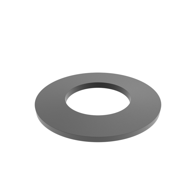
Conical washers with elastic properties, known as disc springs, disc washers or Belleville springs. The DIN 2093 / DIN EN 16983 standard sets out all the dimensional, mechanical and heat-treatment characteristics these parts must meet.
Their main advantage over traditional helical springs is the ability to generate very high elastic forces in comparatively small housings and with small deflections.
By stacking them in series or in parallel, you can tune both the force and the total travel of the assembly to the exact value the application requires. Their elastic properties allow them to work in both dynamic applications (repeated load and unload cycles) and static ones (permanent preload).
The DIN 2093 / DIN EN 16983 standard classifies standard disc springs into three series according to the ratio between the external diameter (De) and the material thickness (t). For each external diameter defined by the standard there are three versions with a different force level — usually referred to by the series letter and the external diameter (for example: A-50 or B-71).
In addition to the three standard series, it is possible to manufacture disc springs with intermediate thicknesses that, while still meeting the standard, do not correspond to any of the three tabulated series.
The DIN 2093 / DIN EN 16983 standard recommends that discs with a thickness greater than 6 mm be manufactured with contact surfaces. These surfaces increase the contact area between the springs, improving stress distribution and reducing wear.
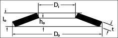
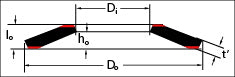
In springs with bearing surfaces, a distinction must be made between the theoretical material thickness (t) and the reduced thickness (t′), which is the actual spring thickness in the contact area. The difference between t and t′ is relevant when designing a parallel stack, since it directly affects the overall height of the assembly.
In the Surisa catalogue you can find the same disc spring with and without contact surfaces; in many cases both versions are interchangeable, but depending on the application one may be more suitable than the other.
Tell us about your use case and our engineering team will help you choose the optimal solution.
The following parameters appear on drawings, calculation sheets and catalogue tables. Getting familiar with the nomenclature is essential to order a reference correctly or to validate a stack.
| Parameter | Meaning |
|---|---|
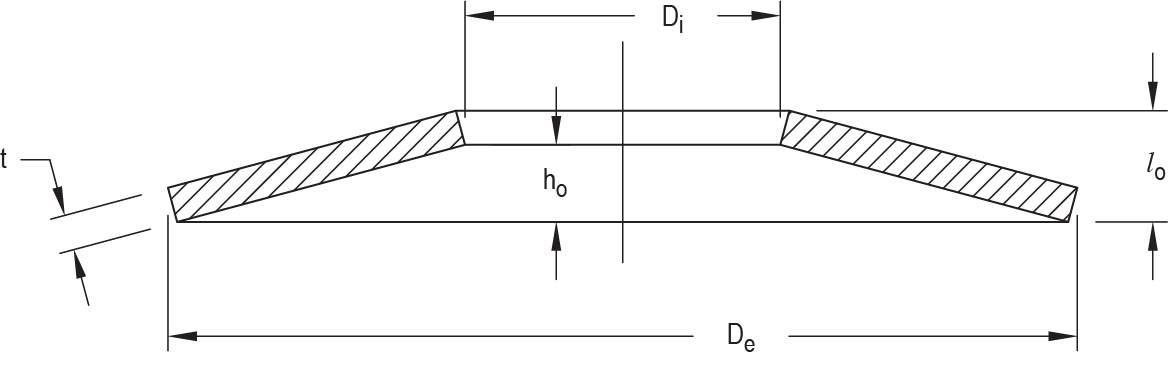
| De | External diameter of the spring |
| Di | Internal diameter of the spring |
| t | Theoretical material thickness |
| lo | Overall free height · lo = t + ho |
| t′ | Reduced thickness — only in disc springs with contact surfaces |
| ho | Maximum deflection · free travel |
| F(0,75 ho) | Force in N at 75% of maximum deflection — recommended dynamic working load |
Overall height formula: lo = t + ho
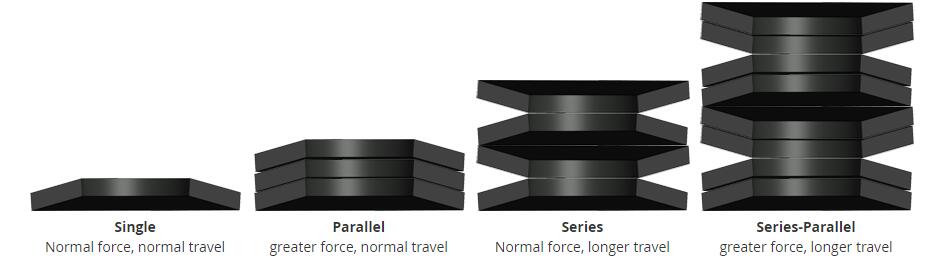
Disc springs can be combined into stacks to obtain custom force and travel characteristics. The choice between series, parallel or a combined configuration is one of the most important design decisions in a disc spring system.
The springs are stacked directly. The total displacement equals that of a single piece; the force increases in proportion to the number of units.
The springs are placed alternating the orientation. The resulting force equals that of a single piece; the total travel is multiplied in direct proportion to the number of units.
Combines the advantages of series and parallel arrangements: increasing the available travel while maintaining high force levels. It also allows springs of different thickness to be combined in the same stack, generating a stepped F/s curve — the thinner springs reach their maximum deflection first and, from that point on, the force required to continue the displacement increases progressively as the stiffness of the remaining stack is higher.
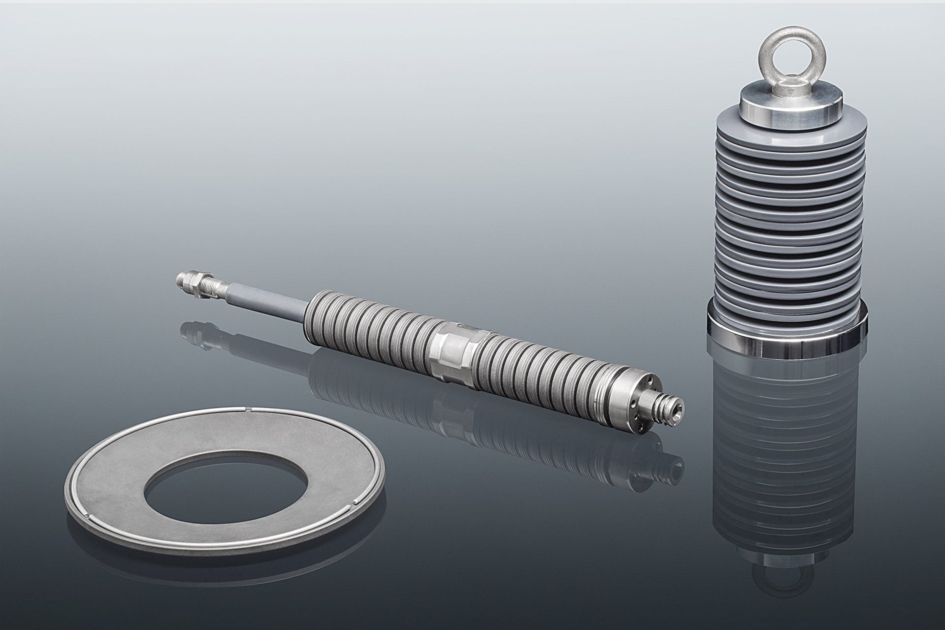
The correct operation of a disc spring stack depends largely on its assembly. The hysteresis produced by friction between the springs themselves and between these and the guide elements can alter the actual force-deflection curve relative to the theoretical one.
The most common method is guidance on the internal diameter by means of a shaft. External guidance by means of a sleeve is also possible, and self-guiding designs exist as well. For the first two options, the tolerances of DIN 2093 / DIN EN 16983 must be observed.
The guide surfaces in contact with the parts must be polished and hardened to a minimum of 55 HRC to a depth of 0.80 mm. In long stacks, flat spacer discs may be required to prevent buckling.
It is essential both between the springs themselves and between these and the guide. The use of molybdenum disulfide (MoS₂) greases is recommended. For applications where friction is critical, special guiding solutions with rings or balls between the parts are available; these replace traditional guidance and eliminate sliding friction (self-guiding).
| Diameter · Di or De (mm) | Tolerance (mm) |
|---|---|
| Up to 16 | 0.2 |
| > 16 to 20 | 0.3 |
| > 20 to 26 | 0.4 |
| > 26 to 31.5 | 0.5 |
| > 31.5 to 50 | 0.6 |
| > 50 to 80 | 0.8 |
| > 80 to 140 | 1.0 |
| > 140 to 250 | 1.6 |
During working cycles, disc springs experience variations in their internal stresses. The amplitude of these variations determines the number of cycles they can withstand before failing by fatigue. For a long service life, it is recommended that they work with a pre-compression of around 15% and a maximum compression that does not exceed 75% of their total deflection.
It cannot be predicted exactly, but knowing the initial and final travel of the dynamic stroke makes it possible to estimate the expected number of cycles. This calculation is especially useful for comparing alternative stacking configurations.
Presetting (or controlled plastic pre-deformation) is a process in which the disc spring is compressed to its flat height (s = h₀) —or even beyond— in order to induce compressive residual stresses in the critical zones, improving its in-service behavior. It is carried out after the tempering heat treatment, once the spring has acquired its final mechanical properties. The localized plastic deformation introduces compressive residual stresses in the outer fibers of the most highly stressed zones (especially at the upper and lower inner edge), and can be performed in one or several passes depending on the spring specifications.
Cold presetting. This is the most common method. The spring is compressed at room temperature to its flat height, exceeding the material's elastic limit in a controlled manner. The compressive residual stresses become fixed in the critical zones once the load is removed.
Hot presetting. The spring is compressed to its flat height while held at an elevated temperature —typically between 200 °C and 500 °C depending on the material— for a set time, then cooled in a controlled manner. Compared with cold presetting, it provides:
On the downside, it requires specific controlled-heating equipment and greater process control, which increases the cost compared with cold presetting.
Effects of presetting. Increased load capacity, improved fatigue resistance, reduced set (loss of free height under sustained load) and dimensional stabilization of the spring before it enters service.
Verification. After presetting, the free height (lo) is checked within tolerance according to DIN 2093, along with the force at nominal deflection on a test bench and the absence of cracks or inadmissible marks on the surface.
Presetting does not replace the heat treatment but rather complements it. Its effect is especially significant in Series C springs (higher h₀/t ratio), owing to the greater plastic deformation possible. The choice between cold and hot presetting must be based on the spring material, the service temperature and the dimensional stability requirements of the application.
Surisa disc springs are manufactured in a wide range of materials, from standard catalogue carbon steel to special alloys for high-temperature service or corrosive environments. The heat treatment and surface finish are decisive for the service life of the stack.
General industrial use · catalogue standard
Corrosion · food · chemical · pharmaceutical
High temperature · extreme environments · aerospace
DIN 2093 / DIN EN 16983 disc springs are used in a wide variety of industrial applications where a high axial force is required in a small space.
Bearing preload, clutch systems, safety valves and pneumatic / hydraulic actuators. The high force per volume allows the spring to be integrated inside valve bodies and transmission housings.
Series-parallel stacks and individual springs to absorb thermal expansion and/or vibration, extending service / maintenance cycles.
Compensation of thermal expansion in boiler structures, steam pipe supports and flexible suspension systems. Alloy steels for high-temperature service.
Tool clamping systems in spindles (drill bit, drill, milling cutter), die preload, hydraulic clamps and presses.
Elastomeric mounts, vibration dampers and anchors.
Flanged joints and absorption of thermal expansion in cold-hot processes. Stainless steel versions in AISI 301 / 304 / 316 for corrosive environments.
DIN 2093 / DIN EN 16983 recommends bearing surfaces when the material thickness exceeds 6 mm. Bearing surfaces increase the contact area between the springs, improving stress distribution and reducing wear in dynamic applications. In parallel stacks it is essential to consider the reduced thickness t′ (instead of t) in order to correctly calculate the overall height of the assembly.
In a series stack (springs opposed, alternating orientation) the force equals that of a single spring and the total displacement is multiplied by the number of pieces. In parallel (same orientation) the displacement is that of a single spring and the force is multiplied by the number of pieces. For combined stacks, Surisa's calculation program obtains the complete force-deflection curve.
Lubrication is essential both between the springs themselves and between these and the guide. The use of molybdenum disulfide (MoS₂) greases is recommended. For applications where friction is critical, special guiding solutions with rings or balls between the parts are available; these replace traditional guidance and also the friction (self-guiding).
Yes. In addition to the standard catalog in carbon spring steel (51CrV4, Ck67, C75S), Surisa manufactures disc springs in stainless steel AISI 301, 304 and 316, as well as in special alloys such as Inconel or Nimonic for high-temperature service. They are also manufactured in diameters and thicknesses different from those suggested by the standard.
Any disc spring subjected to a constant compression load over a prolonged period experiences a gradual loss of force due to material relaxation. To minimise it, all springs manufactured to DIN 2093 / DIN EN 16983 undergo a pre-setting process: they are fully flattened and any that do not recover their initial height are discarded. As a reference, a stack tends to lose around 5% of force in the first two weeks after assembly, stabilising from then on.
Tell us about your use case and our engineering team will help you choose the optimal solution.